Backlight module group and its optical plate

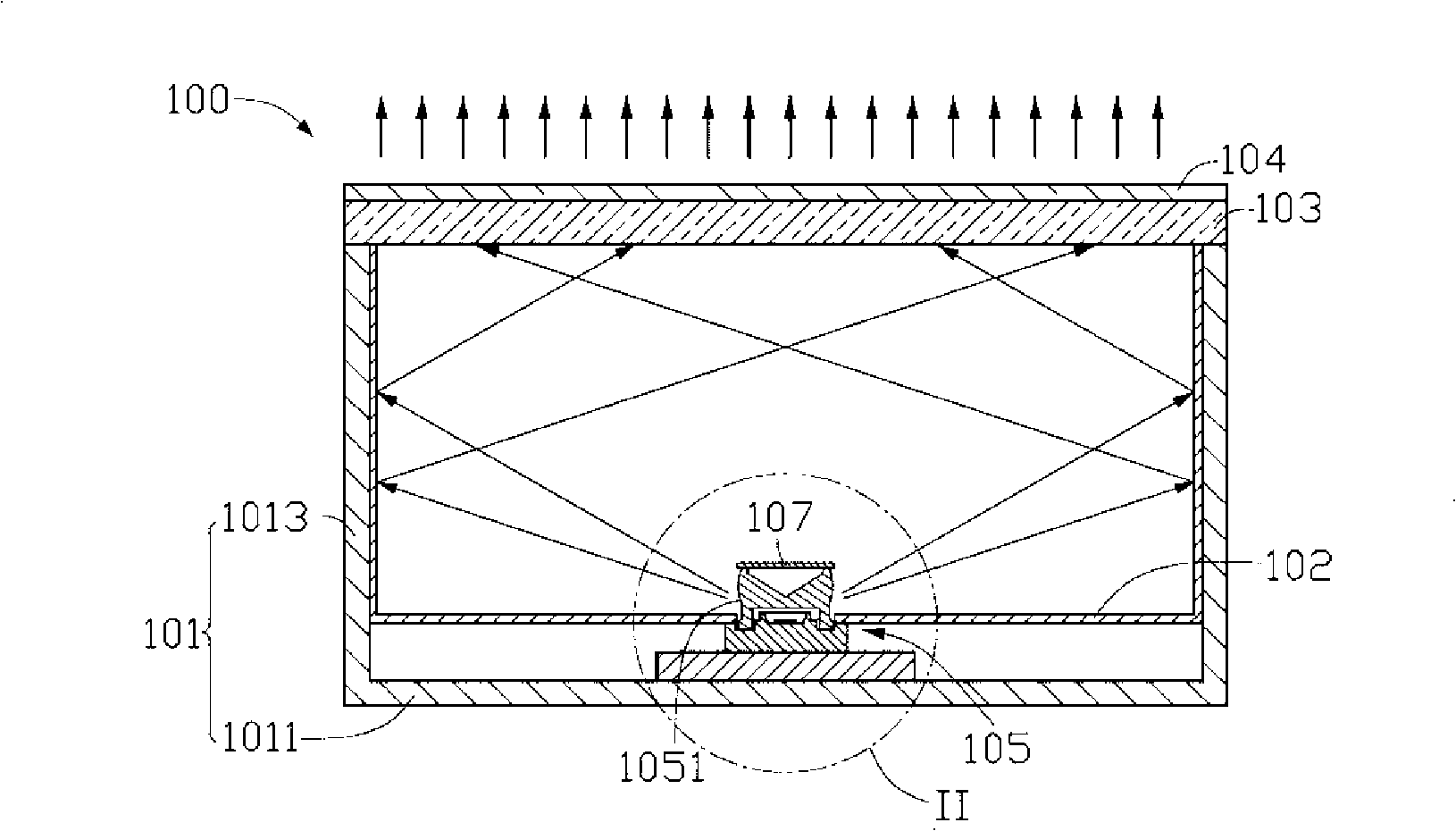
A backlight module and optical board technology, applied in optics, optical components, nonlinear optics, etc., can solve the problem of uneven light output from the backlight module 100, and achieve the effect of improving the uniformity and uniformity of light output

Inactive Publication Date: 2008-10-22
HONG FU JIN PRECISION IND (SHENZHEN) CO LTD +1
View PDF0 Cites 0 Cited by
  • Summary
  • Abstract
  • Description
  • Claims
  • Application Information

AI Technical Summary

Problems solved by technology

The matching design of the light emitting diode 105 and the reflector 107 can eliminate the bright area directly above the light emitting diode 105 to a certain extent, but the backlight module 100 still has the problem of uneven light emission.

Method used


Image

  • Backlight module group and its optical plate
  • Backlight module group and its optical plate
  • Backlight module group and its optical plate

Examples


Embodiment Construction

[0024] The optical plate of the present invention will be further described in detail below with reference to the drawings and multiple embodiments.

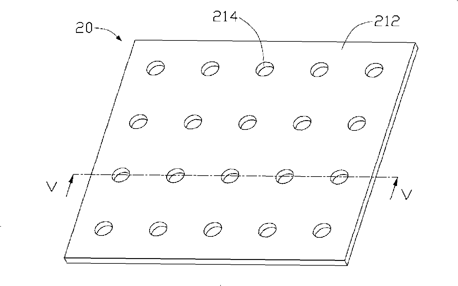
[0025] Please also refer to image 3 , Figure 4 and Figure 5 , the first preferred embodiment of the present invention provides an optical plate 20 . The optical plate 20 has a square shape and includes a plurality of optical plate units 21 arranged closely in an array. Each optical plate unit 21 includes a light emitting surface 212 and a bottom surface 213 opposite to the light emitting surface 212 . The bottom surface 213 is flat, and each bottom surface 213 defines a light source receiving portion 214 and a plurality of grooves 215 at the center thereof, and the plurality of grooves 215 are respectively located around the light source receiving portion 214 . In this embodiment, the light source receiving portion 214 is a through hole penetrating from the bottom surface 213 to the light emitting surface 212 , and the gr...


PUM

PropertyMeasurementUnit
radiusaaaaaaaaaa
depthaaaaaaaaaa

Abstract

The invention relates to a backlight module and an optical plate thereof. The optical plate comprises at least one optical plate unit, the optical plate unit comprises a light leaving surface and a bottom surface opposite to the light leaving surface, and the bottom surface is provided with a light source receiving part and a plurality of grooves. The backlight module adopting the optical plate has the advantage of even light output.

Description

technical field [0001] The invention relates to a backlight module and its optical board, in particular to a backlight module for liquid crystal display and its optical board. Background technique [0002] Since the liquid crystal itself of the liquid crystal display panel does not have luminescent properties, in order to achieve the display effect, it is necessary to provide the liquid crystal display panel with a light source device, such as a backlight module. The function of the backlight module is to supply a surface light source with sufficient brightness and uniform distribution to the LCD panel. [0003] Please also see figure 1 and figure 2 , shows a conventional backlight module 100 , which includes a frame 101 , a reflector 102 , a diffuser 103 , a prism sheet 104 and at least one LED 105 . The frame 101 includes a bottom plate 1011 and a plurality of sidewalls 1013 vertically extending from an edge of the bottom plate 1011 to one side thereof. The bottom pla...

Claims


Application Information

Patent Timeline
Patent Type & Authority Applications(China)
IPC IPC(8): G02B6/00G02F1/13357G02F1/1335
CPCG02B6/0031G02B6/0021G02B6/0036G02F1/133606
Inventor 章绍汉
Owner HONG FU JIN PRECISION IND (SHENZHEN) CO LTD
Why Eureka
Try Eureka