

Luffing jib maintaining valve for hydraulic shovel
A technology for hydraulic excavators and holding valves, applied to mechanically driven excavators/dredgers, etc., can solve problems such as potential safety hazards, lower booms, accidents, etc., and achieve the effect of reducing the sinking of the boom
- Summary
- Abstract
- Description
- Claims
- Application Information
AI Technical Summary
Problems solved by technology
Method used
Image

Examples
Embodiment Construction
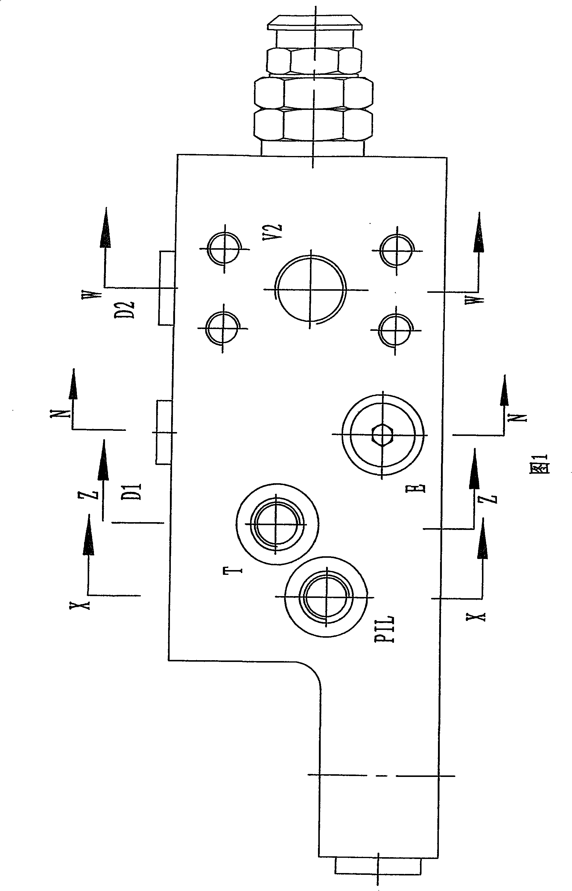
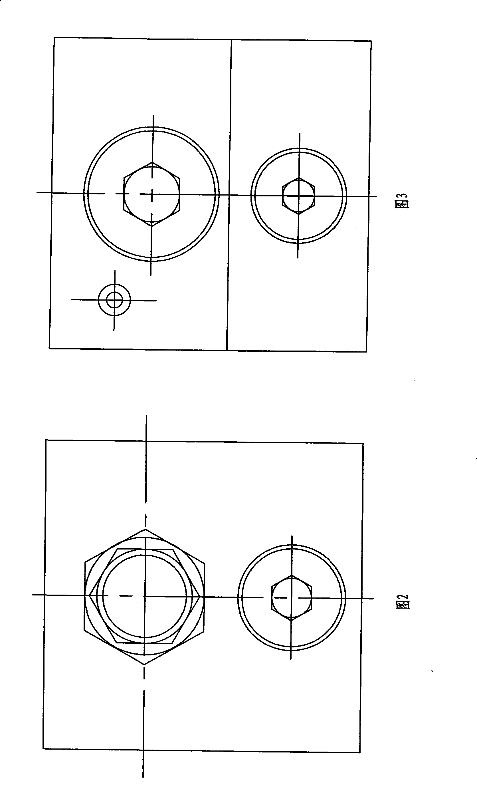
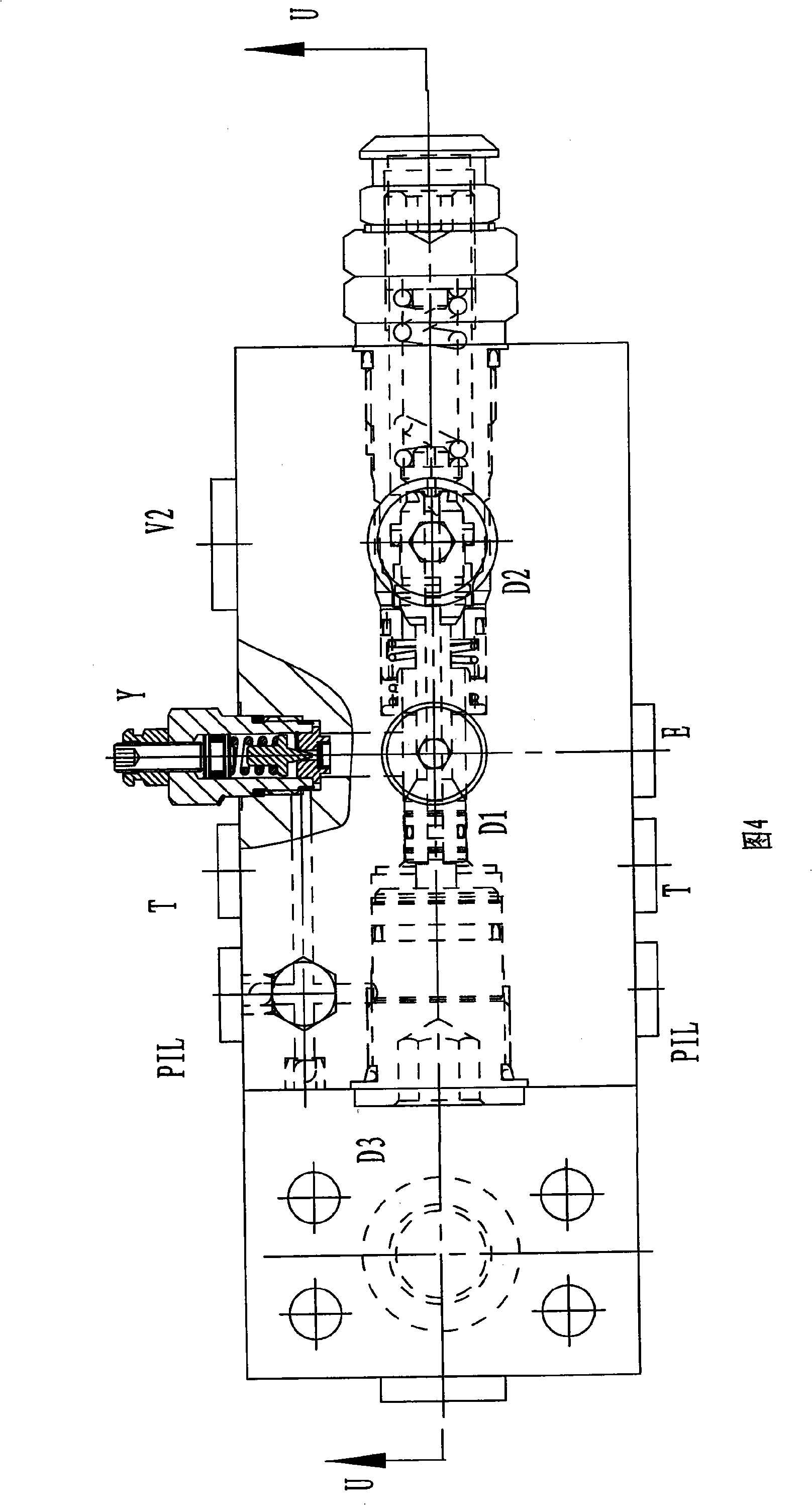
[0020] As shown in Figs. 1 to 9, the present invention is a hydraulic excavator boom holding valve, including a valve block 1, a first valve hole and a second valve hole are opened in the valve block 1, and the first valve hole and the second valve hole are opened in the valve block 1. The valve holes are parallel to each other.
[0021] Piston 4, valve rod 6, left spring seat I 8, spring I 9, right spring seat I 11 and holding valve 14 are arranged in the first valve hole from left to right, and the cone core I 20 of holding valve 14 is in contact with the The valve stem 6 is connected, the outer edge of the cone core I 20 is provided with an O-ring IV21 and a retaining ring I 22, the right end is provided with an O-ring III 19, the outer edge of the piston 4 is provided with a combined sealing ring I 5, and the right spring seat I The outer edge of 11 is provided with a combined sealing ring III10, the left end of the first valve hole is screwed with a plug I2, and the outer...
PUM
 Abstract
Description
Claims
Application Information