Method for conveying electric power and serial bus signal based on Ethernet cable
A serial bus and Ethernet technology, applied in the field of automatic monitoring, can solve the problems of high price and occupation of Ethernet controller modules, and achieve the effect of convenient installation and low cost
Inactive Publication Date: 2008-10-29
范良凯
View PDF3 Cites 13 Cited by
- Summary
- Abstract
- Description
- Claims
- Application Information
AI Technical Summary
Problems solved by technology
In the prior art, Chinese patents "A Transmitter Capable of Realizing Ethernet Communication and Powered by Network Redundancy" (Patent No.: 01132306.X), "Real-time Industrial Ethernet Pressure Transmitter" (Patent No.: 200520142082 .X) and "Real-time Industrial Ethernet Temperature Transmitter" (Patent No.: 200520142083.4) and other patents can realize data acquisition and power supply functions based on Ethernet cables, but their necessary Ethernet controller modules are expensive and require Occupies an Ethernet information point
Method used
View moreImage
Smart ImageViewing Examples
Examples
Embodiment 1
Embodiment 2
Login to View More PUM
 Abstract
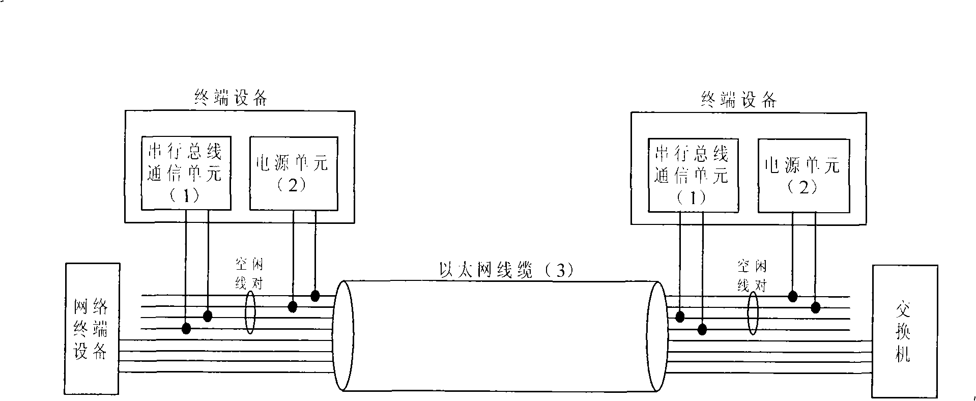
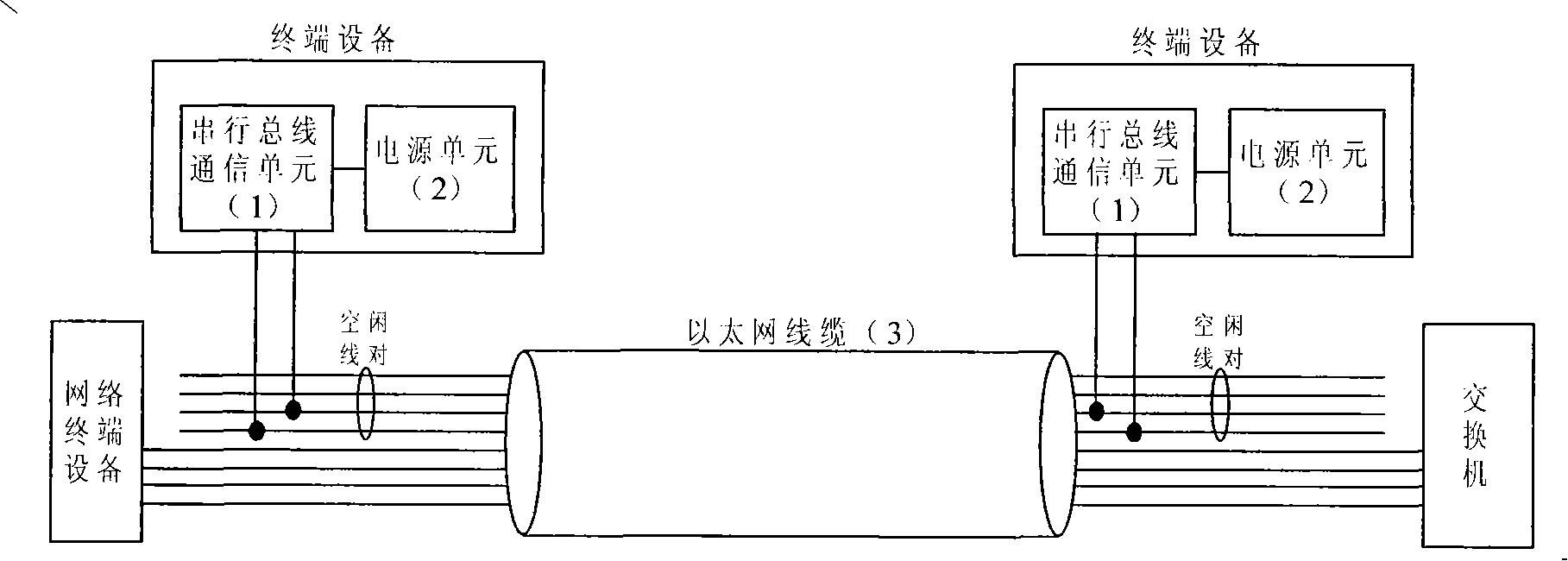
The invention relates to a method for transmitting power and universal serial bus (USB) signals based on Ethernet cables. The method comprises the following steps : an idle line pair in the Ethernet cables comprising four line pairs is coupled to a power transmission system, and another idle line pair is coupled to a communication system of the USB, and the line pairs supply power and communication signal transmission trackways to terminal equipment. After adopting the proposal, front end terminal equipment serial-communicates with rear end terminal equipment by the idle line pairs in the Ethernet cables, and the rear end terminal equipment supplies power to the front terminal equipment by the idle line pairs in the Ethernet cables, therefore, the front terminal equipment does not need field power supplying.
Description
Method for transmitting power and serial bus signal based on Ethernet cable 1. Technical field The invention relates to the field of automatic monitoring, in particular to a method for transmitting power and serial bus signals based on Ethernet cables. 2. Background technology In the prior art, Chinese patents "A Transmitter Capable of Realizing Ethernet Communication and Powered by Network Redundancy" (Patent No.: 01132306.X), "Real-time Industrial Ethernet Pressure Transmitter" (Patent No.: 200520142082 .X) and "Real-time Industrial Ethernet Temperature Transmitter" (Patent No.: 200520142083.4) and other patents can realize data acquisition and power supply functions based on Ethernet cables, but their necessary Ethernet controller modules are expensive and require Occupies an Ethernet information point. 3. Contents of the invention (1) Purpose of the invention In view of the problems to be solved in the above-mentioned prior art, the purpose of the present inventi...
Claims
Login to View More Application Information
Patent Timeline
 IPC IPC(8): H04L12/10H04B3/54
Inventor 范良凯
Owner 范良凯
Features
- R&D
- Intellectual Property
- Life Sciences
- Materials
- Tech Scout
- Unparalleled Data Quality
- Higher Quality Content
- 60% Fewer Hallucinations
Learn More Browse by: Latest US Patents, China's latest patents, Technical Efficacy Thesaurus, Application Domain, Technology Topic, Popular Technical Reports.
© 2025 PatSnap. All rights reserved.Legal|Privacy policy|Modern Slavery Act Transparency Statement|Sitemap|About US| Contact US: help@patsnap.com


