Eureka AIR delivers breakthrough ideas for toughest innovation challenges, trusted by R&D personnel around the world.

Calibration device and method with forward/backward mechanism for band-pass filter

A calibration method and technology of a calibration device are applied to a single resonant circuit with variable inductance and capacitance at the same time, the adjustment of the resonant circuit, the components of the resonant circuit, etc. And other issues

Inactive Publication Date: 2008-10-29
NXP BV
View PDF1 Cites 2 Cited by
  • Summary
  • Abstract
  • Description
  • Claims
  • Application Information

AI Technical Summary

Problems solved by technology

This method is not practically accurate and does not allow judgments to be made in real time

Method used


Image

  • Calibration device and method with forward/backward mechanism for band-pass filter
  • Calibration device and method with forward/backward mechanism for band-pass filter
  • Calibration device and method with forward/backward mechanism for band-pass filter

Examples


Embodiment Construction

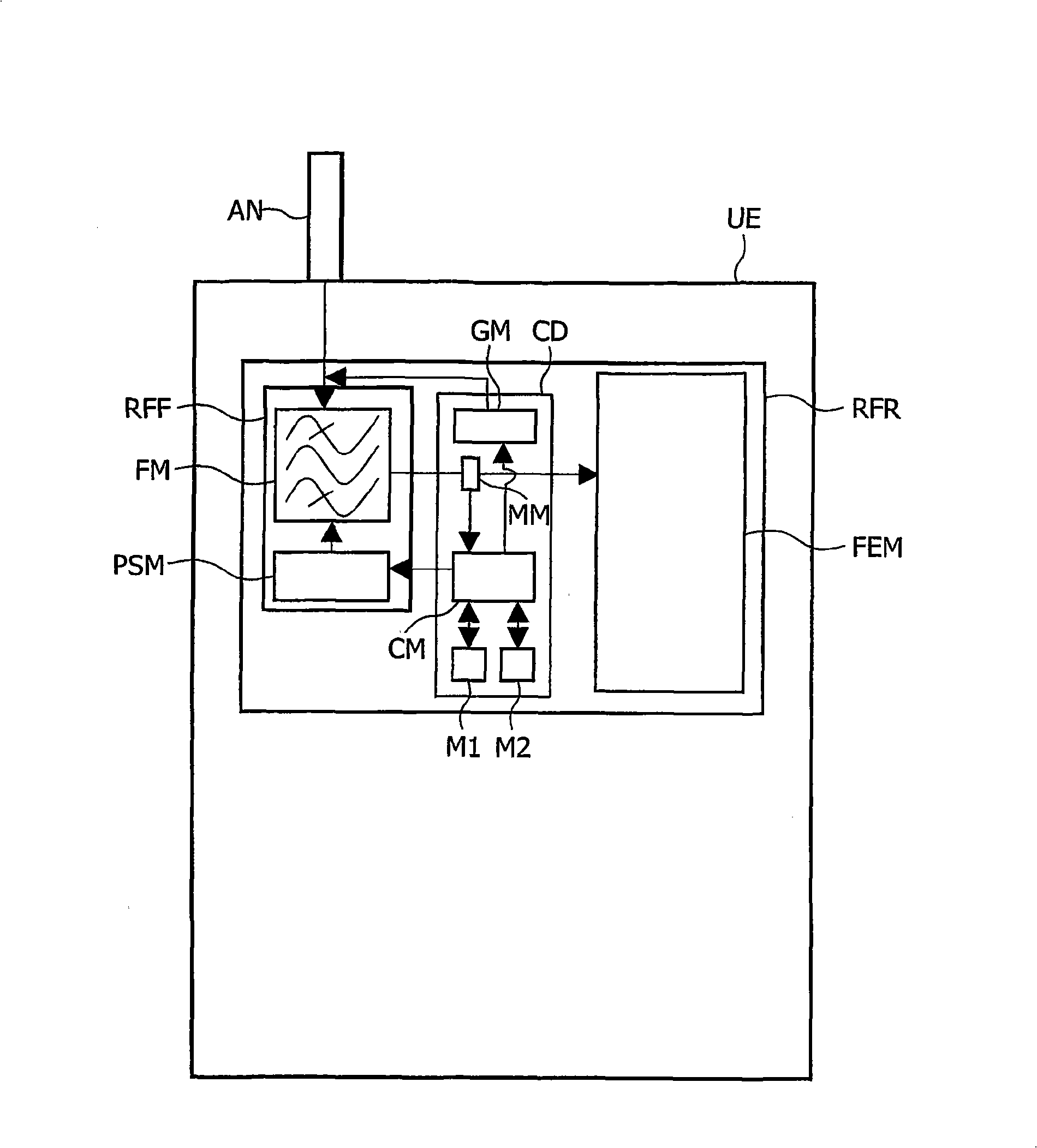
[0047] like figure 1 As shown, the invention provides a calibration device CD dedicated to a radio frequency (RF) communication receiver RFR which can be implemented in an RF communication device UE.

[0048]In the following description, the RF communication device UE may be considered as a mobile phone, eg a GSM / GPRS or UMTS mobile phone. But it is important to note that the present invention is not limited to such RF communication devices.

[0049] The present invention is indeed applicable to any RF communication device, mobile (or stationary) device and in particular a Personal Digital Assistant (PDA), or a laptop including a communication module adapted to establish a wireless communication, or other wireless (AM, FM), or in television (TV) tuners or televisions connected to set-top boxes (STBs).

[0050] like figure 1 As shown, the RF communication receiver RFR comprises an RF front-end module FEM fed by an RF front-end filter RFF connected to the input of an antenna ...


PUM


Abstract

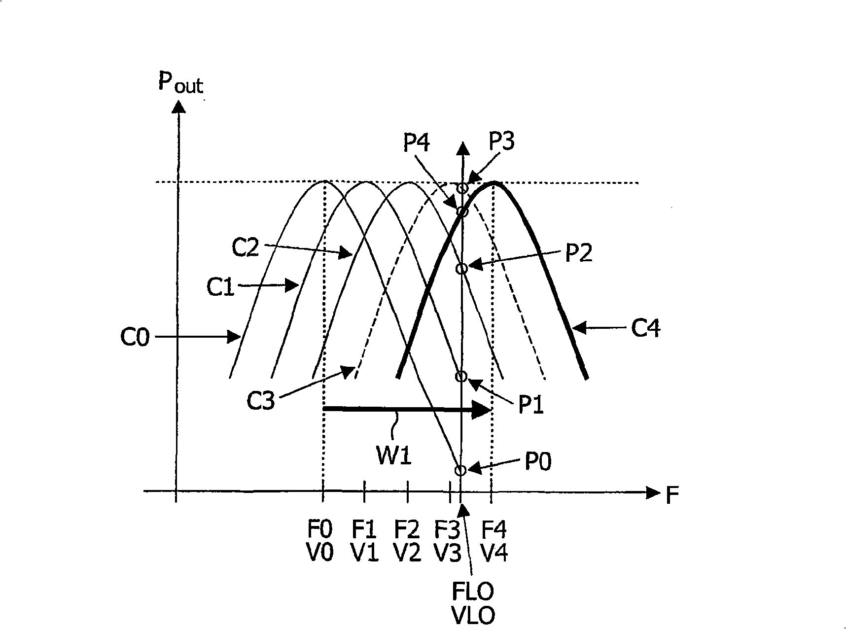
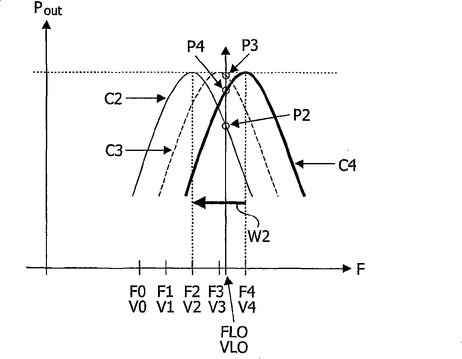
A calibration device (CD) is dedicated to a RF band-pass filter (RFF) comprising a means (FM) for filtering a frequency band depending on the value of a control voltage applied by a controllable power supply means (PSM). This device (CD) comprises i) a generator (GM) for feeding the filter means (FM) with a test signal of a chosen frequency, ii) a means (MM) arranged to measure the output power values of the test signal at the filter means output, and iii) a control means (CM) arranged a) to order the power supply means (PSM) to apply successive increasing control voltages as long as the output power value increases, reaches a maximum value and then begins to decrease, then b) to store the first decreasing output power value and the corresponding control voltage, then c) to order the power supply means (PSM); to apply successive decreasing control voltages as long as the output power value increases, reaches said maximum value and then begins to decrease to a last output power value, and then d) to determine a control voltage corresponding to a maximum of the filter output power at the chosen frequency from the stored control voltage and the control voltage applied last and corresponding to the last output power value.

Description

technical field [0001] The present invention relates to the field of radio frequency (RF) signal filtering, and more particularly to the calibration of RF bandpass filters in RF communication receiver devices. Background technique [0002] As is known to those skilled in the art, RF communication receivers typically include RF front-end filters to reject power contained in undesired channels adjacent to the transmission channel. Such suppression enables the RF communication receiver to satisfy the linearity requirement mandatory for channel selection, and to reduce the power consumption of the communication device in which the RF communication receiver is installed. [0003] In RF communication equipment, especially terrestrial equipment dealing with a large input frequency range (typically from 50Mhz to 1GHz), the filter must be a tracking bandpass filter which needs to be tuned exactly to the desired frequency. [0004] Most tuning devices use a superheterodyne structure ...

Claims


Application Information

Patent Timeline
Patent Type & Authority Applications(China)
IPC IPC(8): H04B1/18H03H7/01H03J1/00
CPCH03J3/00H04B1/18H03J2200/08H03J3/22
Inventor 让-罗伯特·图雷特
Owner NXP BV
Why Eureka
Eureka Blog
Learn More