
Groove processing method and forming rotary cutting tool

A technology of cutting tools and processing methods, which is applied in the field of groove processing methods and forming rotary cutting tools, can solve problems such as difficult cutting speed groove processing, achieve efficient groove processing, and increase cutting speed and feed rate.

Inactive Publication Date: 2011-06-15
OSG
View PDF1 Cites 0 Cited by
  • Summary
  • Abstract
  • Description
  • Claims
  • Application Information

AI Technical Summary

Problems solved by technology

This makes it difficult to efficiently groove by increasing cutting speed and feed rate

Method used


Image

  • Groove processing method and forming rotary cutting tool
  • Groove processing method and forming rotary cutting tool
  • Groove processing method and forming rotary cutting tool

Examples


Embodiment Construction

[0051] DETAILED DESCRIPTION OF THE PREFERRED EMBODIMENTS Preferred embodiments of the present invention will be described below with reference to the accompanying drawings.

[0052]

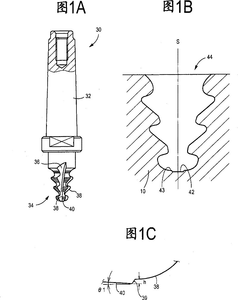
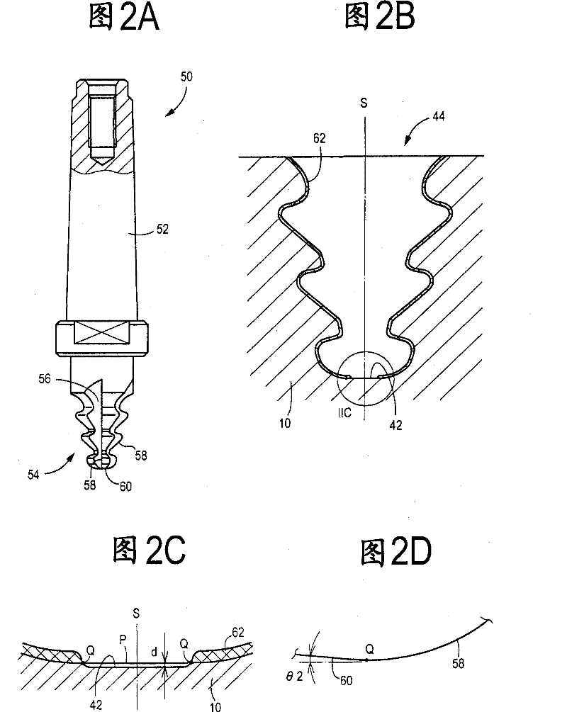
[0053] Figure 1 shows a Christmas tree cutter 30 for roughing and Figure 2 shows a Christmas tree cutter 50 for finishing, both of the milling cutter type. Both cutters 30 and 50 are used for cutting the above-mentioned tree-shaped groove 12 of FIG. Move vertically. The roughing Christmas tree tool 30 , sometimes referred to as a "roughing tool", corresponds to the claimed roughing forming rotary cutting tool for forming the roughing groove 22 .

[0054] In this embodiment, the roughing tool 30 is used to form a roughing groove 44 provided with a groove 42 on its bottom surface 43 . The roughing tool 30 cuts the roughing groove 44 in a single step or pass. The Christmas tree tool 50 for finishing, sometimes referred to as a "finishing tool", corresponds to the claimed finishing shaped rotary...


PUM


Abstract

The process involves cutting a roughly machined groove (44) in a workpiece i.e. rotary shaft (10), by moving a molded roughing rotary cutting tool in a direction perpendicular to an axis relative to the workpiece by rotating the molded roughing rotary cutting tool around an axis. The groove is smoothed in the workpiece by moving the cutting tool in a direction perpendicular to the axis relative to the workpiece by rotation of the molded smoothing rotary cutting tool around the axis. A base section (43) of the roughly machined groove is unsmoothed by the molded smoothing rotary cutting tool. Independent claims are also included for the following: (1) a kit of molded rotary cutting tools for cutting a groove of a pre-determined shaped in a workpiece (2) a molded roughing rotary cutting tool, comprising a trailing edge.

Description

technical field [0001] The present invention relates to a grooving method and a profiled rotary cutting tool, and more particularly to a technique for reducing the cutting torque required for finishing a rough-machined groove, thereby efficiently performing grooving. Background technique [0002] FIG. 7 shows a configuration in which a turbine wheel such as a gas turbine is mounted on the rotary shaft 10 . In this configuration, a plurality of blades 14 are respectively fitted in a plurality of tree-shaped grooves 12 formed in the outer circumference of the rotary shaft 10 . FIG. 8 is an enlarged cross-sectional view showing one of the tree-like grooves 12 . As clearly shown in FIG. 8, the groove 12 has an inverted Christmas tree shape in cross-section, which is laterally (left-right) symmetrical with respect to its groove centerline S. As shown in FIG. In the groove depth direction from the outer peripheral surface toward the axis of the rotating shaft 10 , that is, in th...

Claims


Application Information

Patent Timeline
Patent Type & Authority Patents(China)
IPC IPC(8): B23C3/34B23C5/12
CPCB23C5/10B23C3/30B23C2220/366
Inventor 都筑清志
Owner OSG
Learn More