
Grinding and milling drill with drill tip capable of breaking chips

A drill tip and chip breaking technology, which is applied in drilling/drilling equipment, drill repairing, twist drills, etc., can solve problems such as large changes in the rake angle, difficult flow of cutting fluid, and large speed differences. Good chips, reduced cutting torque, and increased feed rate

Pending Publication Date: 2020-04-14
JIANGSU TIANGONG PRECISION TOOLS CO LTD
View PDF0 Cites 0 Cited by
  • Summary
  • Abstract
  • Description
  • Claims
  • Application Information

AI Technical Summary

Problems solved by technology

[0002] The traditional ordinary twist drill, since its birth for more than a hundred years, its structural shape has not changed much. With the continuous development of science and technology, new materials are constantly emerging, and new requirements are constantly being put forward for the drill bit. However, the traditional ordinary twist drill mainly has the following problems: 1. The value of the rake angle at each point on the main edge changes greatly, and the position close to the drill core has a negative rake angle, and the cutting conditions are poor
2. The chisel edge is too long, with a large edge angle, =90°, and a large negative rake angle, and the cutting conditions are even worse, so the axial resistance is large and the centering is not good
3. The main edge is long and the chip is wide. The speed of chip flow at each point varies greatly. The chip curls into a wide spiral, which occupies a large space, resulting in poor chip removal and difficult flow of cutting fluid.

Method used


Image

  • Grinding and milling drill with drill tip capable of breaking chips
  • Grinding and milling drill with drill tip capable of breaking chips

Examples


Embodiment Construction

[0016] In order to deepen the understanding of the present invention, the present invention will be described in further detail below in conjunction with the accompanying drawings and embodiments, which are only used to explain the present invention and do not limit the protection scope of the present invention.

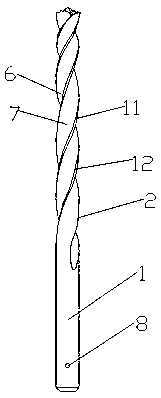
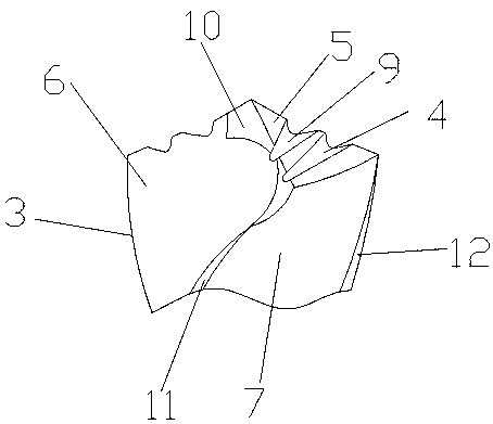
[0017] As shown in the figure, this embodiment provides a drill tip chip breaking milling drill, which includes a drill shank 1 and a twist-shaped cutter body 2, the drill shank 1 is a straight shank, and the top end of the cutter body 2 is a drill tip 3, The drill tip 3 is provided with two main cutting edges 4 and two symmetrical flanks 5, the outer wall of the cutter body 2 is provided with a helical spiral groove 6 and a back 7, the drill shank 1 A plurality of positioning holes 8 are uniformly arranged along the outer periphery, and the drill tip 3 is provided with two chip dividing grooves 9 around the flank 5, and the two rear flute edges of the drill tip 3 are...


PUM


Abstract

The invention discloses a grinding and milling drill with a drill tip capable of breaking chips. The grinding and milling drill comprises a drill shank and a twist-shaped tool body, the top end of thetool body is provided with the drill tip, the drill tip is provided with two main cutting edges and two mutually symmetrical flank faces, the outer wall of the tool body is provided with a spiral groove and an edge back which are spiral shaped, the drill tip is provided with at least one chip dividing groove in the flank faces in a surrounding mode, and a grinding face is formed by simultaneouslygrinding two rear groove edges of the drill tip in the direction of a transverse edge and grinding a tail root edge of the top of the tool body. According to the grinding and milling drill, the structure is simple, the design is reasonable, after the transverse edge and the chip dividing groove are ground, the feeding amount can be increased, the efficiency can be improved, and chip discharging is good.

Description

technical field [0001] The invention belongs to the technical field of tools, and in particular relates to a twist drill, especially a drill tip chip breaking milling drill. Background technique [0002] The traditional ordinary twist drill, since its birth for more than a hundred years, its structural shape has not changed much. With the continuous development of science and technology, new materials are constantly emerging, and new requirements are constantly being put forward for the drill bit. However, the traditional ordinary twist drill mainly has the following problems: 1. The value of the rake angle at each point on the main edge varies greatly, and the position close to the drill core has a negative rake angle, and the cutting conditions are poor. 2. The chisel edge is too long, with a large edge angle, =90°, and a large negative rake angle, and the cutting conditions are even worse, so the axial resistance is large and the centering is not good. 3. The main edge i...

Claims


Application Information

Patent Timeline
Patent Type & Authority Applications(China)
IPC IPC(8): B23B51/08B23B51/02B23B47/34
CPCB23B51/08B23B51/02B23B47/34
Inventor 朱小坤何建国
Owner JIANGSU TIANGONG PRECISION TOOLS CO LTD
Learn More