Twist drill with front angle correction and machining method of twist drill

A processing method, twist drill technology, applied in twist drills, metal processing equipment, drilling/drilling equipment, etc., can solve the problems that the difference in the contour of the grinding wheel cannot be too large, it is unfavorable for the batch production of twist drills, and the twist drills cannot be used. Achieve the effects of shortening processing time, increasing sharpness, and delaying built-up edge

Active Publication Date: 2021-04-06
ZHUZHOU CEMENTED CARBIDE CUTTING TOOLS CO LTD
View PDF6 Cites 1 Cited by
  • Summary
  • Abstract
  • Description
  • Claims
  • Application Information

AI Technical Summary

Problems solved by technology

However, due to the multiple times of grinding with the formed grinding wheel, it takes a very long time to achieve the precision grinding effect of the Ra0.1 mirror surface. One specification product requires two grinding wheels with different particle sizes, and the processing cost is too high. It is not conducive to the mass production of twist drills of different specifications; at the same time, the difference in the profile of two grinding wheels with different grain sizes should not be too large, otherwise the groove shape of the drill bit will change, resulting in a mismatch between the drill tip structure and the groove shape, and the twist drill cannot be used.

Method used


Image

  • Twist drill with front angle correction and machining method of twist drill
  • Twist drill with front angle correction and machining method of twist drill
  • Twist drill with front angle correction and machining method of twist drill

Examples


Embodiment 1

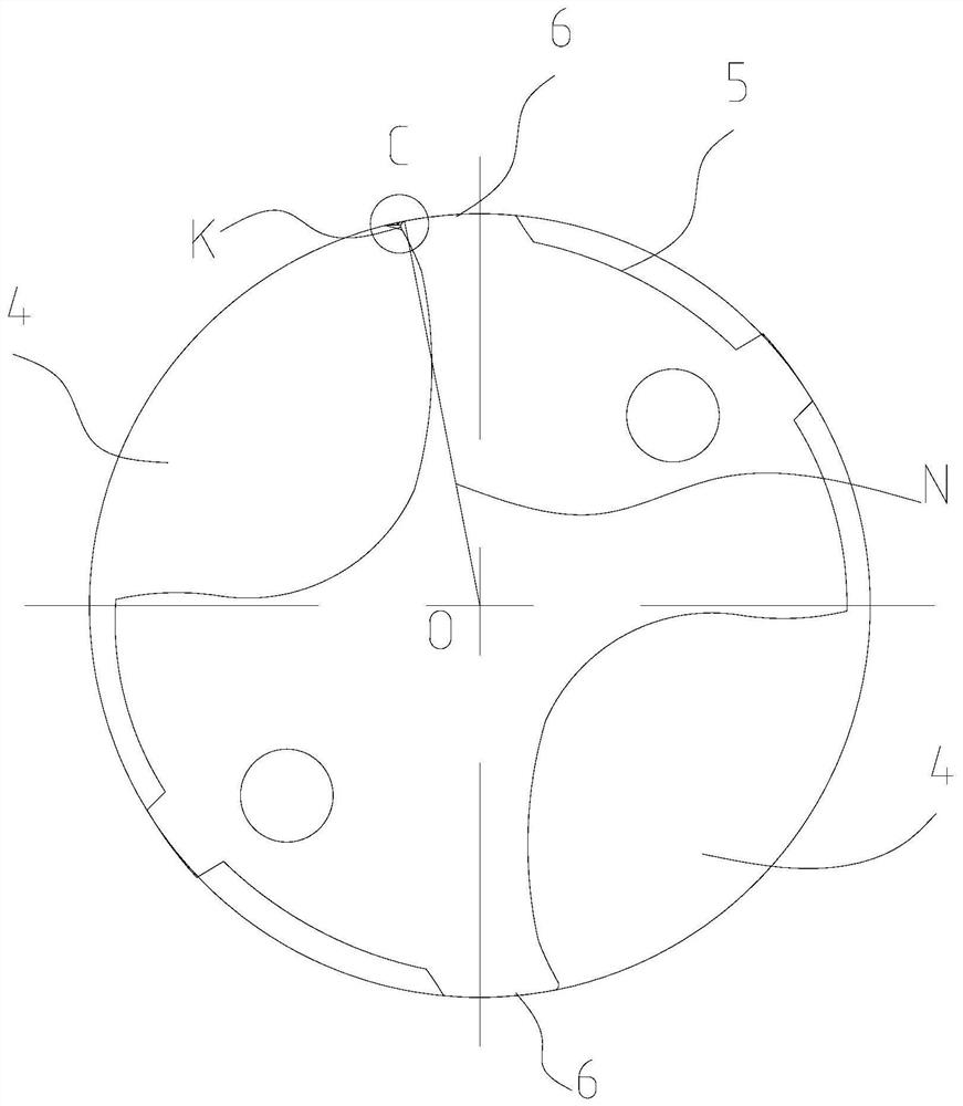
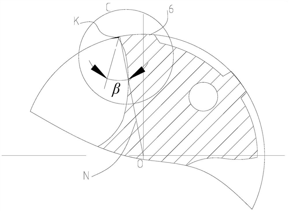
[0039] Such as Figure 5 to Figure 9 As shown, the twist drill with rake angle correction in this embodiment includes a cutting part 1 and a shank part 2. The front end of the cutting part 1 is provided with a drill point 3, and the cutting part 1 is provided with two wires extending from the drill point 3 to the shank part. 2 spiral chip flutes 4, the part of the cutting part 1 between the two spiral chip flutes 4 constitutes the blade 5, in the direction of the rotary cutting of the twist turn ( Figure 6 Arrow E in the figure), the front end of the blade 5 is provided with a main land 6, the main land 6 is a circumferential cutting edge, and the drill tip 3 is a face cutting edge. In the section perpendicular to the cutting part 1, the spiral flute 4 is connected to the main land 6 through a rake angle correction surface 7, and the line connecting the front end point M of the main land 6 and the center O of the blade 5 is a line N, The rake angle correction surface 7 is co...

Embodiment 2

[0048] The processing method of the twist drill of the present embodiment is used to process the twist drill of embodiment 1, and the method comprises the following steps:

[0049] S1. Grinding the spiral chip flute 4 of the twist drill with a coarse-grained forming grinding wheel. At this time, there is a sharp angle P between the spiral chip flute 4 and the main edge 6;

[0050] S2. Use a polishing brush to polish the spiral chip flute 4 until it reaches the Ra0.1 mirror surface precision grinding effect. At this time, use the polishing brush to grind the sharp corner P into a rounded corner K;

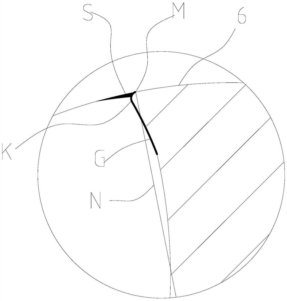
[0051] S3. Grinding the fillet K with a fine-grained grinding wheel, so that the fillet K protruding relative to the line N becomes a concave rake angle correction surface 7 .

[0052] In this embodiment, in step S2, the polishing brush is polished twice to check the spiral chip flute 4, if the spiral chip flute 4 reaches R0.1 mirror surface precision grinding effect, stop polishing...


PUM


Abstract

The invention discloses a twist drill with front angle correction and a machining method of the twist drill. The twist drill comprises a cutting part and a handle part; the front end of the cutting part is provided with a drill tip; the cutting part is provided with two spiral chip grooves extending from the drill tip to the handle part; the portion, between the two spiral chip grooves, of the cutting part forms a blade petal; the front end of the blade petal is provided with a main blade belt; the spiral chip grooves are connected with the main blade belt through a front angle correction face; in the section perpendicular to the cutting part, the connecting line of the front end point M of the main blade belt and the center O of the blade petal is a line N; the front angle correction face is concave inwards relative to the line N; and the front angle of the front angle correction face is gamma, and gamma is a positive acute angle. The machining method comprises the steps of rough grinding, brush fine grinding, front angle correction surface grinding and the like. According to the twist drill with front angle correction and the machining method of the twist drill, the sharpness of the twist drill is improved easily, the cutting torque of the twist drill is reduced, the risk of built-up edges generated in the drilling process is reduced, the drilling precision is greatly improved, the service life is greatly prolonged, the brush polishing process is adopted, the manufacturing cost of the twist drill can be greatly saved, and the production efficiency of the twist drill can be greatly improved.

Description

technical field [0001] The invention relates to cutting processing, in particular to a twist drill with rake angle correction and a processing method for the twist drill. Background technique [0002] Deep hole processing generally refers to hole processing with an aperture ratio greater than 5. Deep hole machining is a difficult point in drilling. During the drilling process of soft materials (such as aluminum alloy materials, etc.), machining vibrations are prone to occur, resulting in out-of-tolerance straightness and roundness of the processed holes, and even built-up edge. As a result, the cutting force increases sharply, the torque increases, and finally the tool breaks and the parts are scrapped. Therefore, chip evacuation and safety are key concerns in deep hole drilling. [0003] Such as Figure 1 to Figure 4 As shown, in the process of polishing the spiral flute, since the polishing brush is easy to polish the main land 6 on the outer periphery, a fillet K (circl...

Claims


Application Information

Patent Timeline
Patent Type & Authority Applications(China)
IPC IPC(8): B24B1/00B24B3/24B23B51/02
CPCB24B1/00B24B3/24B23B51/02
Inventor 肖跃勇方曙璋李华建曾滔罗胜
Owner ZHUZHOU CEMENTED CARBIDE CUTTING TOOLS CO LTD
Why Eureka
Try Eureka