Tubular actuator for powering a screen and method for manufacturing such an actuator

A technology of actuators and shields, applied in building construction, connection with control/drive circuits, electric components, etc., can solve problems such as damaged threads and non-removal

Active Publication Date: 2008-11-12
SOMFY ACTIVITES SA
View PDF1 Cites 16 Cited by
  • Summary
  • Abstract
  • Description
  • Claims
  • Application Information

AI Technical Summary

Problems solved by technology

The second constraint is the risk of damaging the thread when the thread is made of plastic and the screw torque is too high, for example due to poor adjustment of the screw drive
The component turned out to be non-removable, which is undesirable in the case of subsequent repair interventions

Method used


Image

  • Tubular actuator for powering a screen and method for manufacturing such an actuator
  • Tubular actuator for powering a screen and method for manufacturing such an actuator
  • Tubular actuator for powering a screen and method for manufacturing such an actuator

Examples


Embodiment Construction

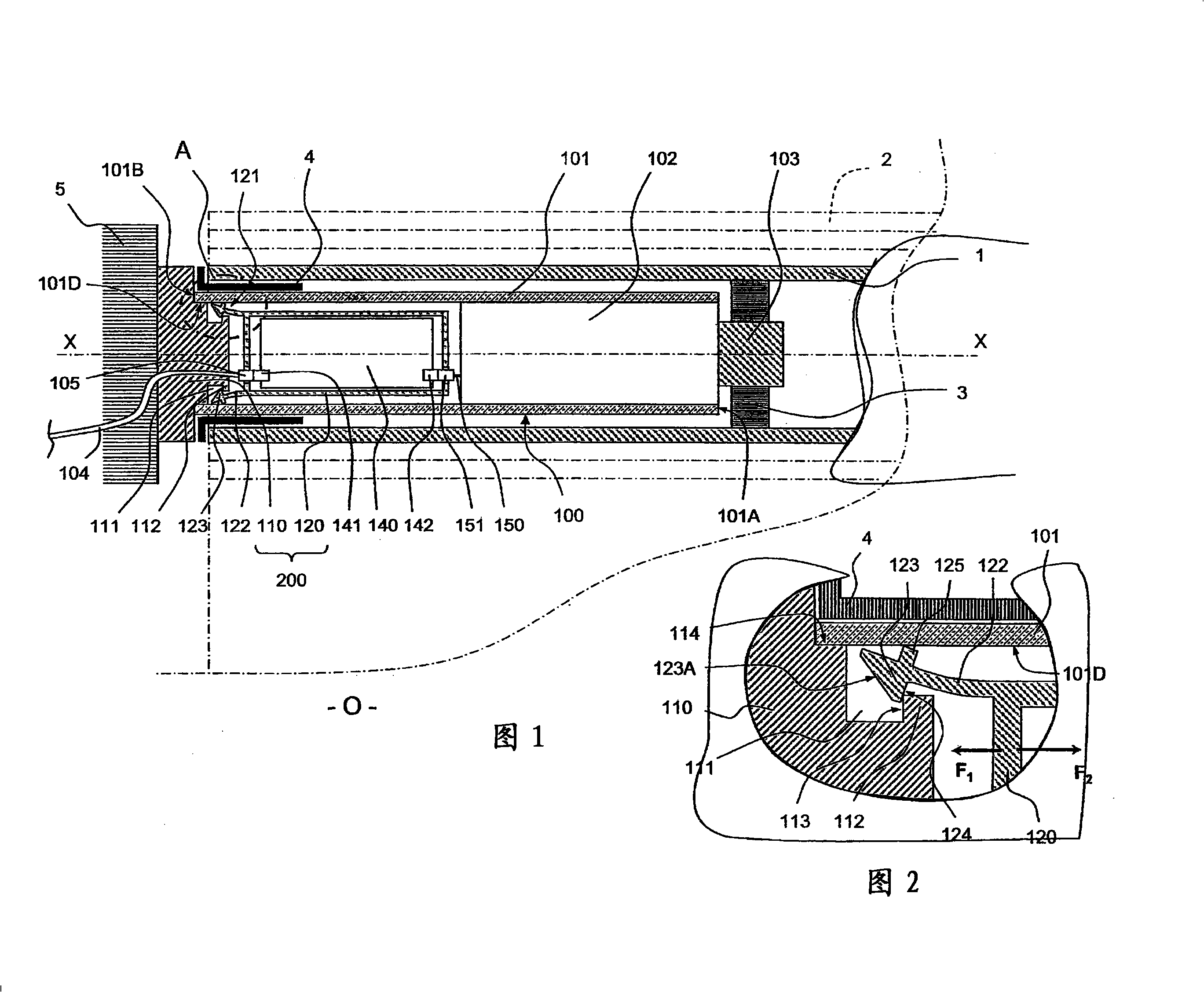
[0034] Figure 1 shows a tubular actuator 100 for driving a roller shade tube 1 on which a curtain 2 for sealing an opening O can be wound to a greater or lesser extent. The tube 1 is driven by an actuator 100 in rotation about an axis of rotation X-X lying horizontally at the top of this opening. The opening O is, for example, an opening formed in a wall of a building. Thus, the actuator 100, the tube 1 and the shade 2 form a motorized roller shade.

[0035] The actuator 100 includes a cylindrical tube 101 in which is mounted a gear motor 102 comprising an electric motor, a brake and a reduction gear, and is equipped with an output shaft 103 protruding from one end 101A of the tube 101 and driving Crown gear 3 engaged in rotation with tube 1 .

[0036] The roller shutter tube 1 rotates about the axis X-X and the fixed tube 101 thanks to two pivot joints. The ring support 4 mounted on the outer periphery of the tube 101 near the end 101B of the tube 101 opposite the end 101A...


PUM


Abstract

The actuator (100) has a fixation piece (110) integrating the actuator with a frame (5) and partially arranged inside a tube (101) of the actuator. A case (120) houses a control part i.e. electronic board (140), that controls supply of an electric motor of a gear motor (102) belonging to the actuator, where the case and the motor are arranged inside the tube. Assembling units are formed of clips (121) for assembling the piece and the case. A locking unit locks the clips between the piece and the case, when the case is placed in the tube, and is formed by an inner surface (101D) of the tube. An independent claim is also included for a method of manufacturing a tubular actuator.

Description

technical field [0001] The present invention relates to a tubular actuator for driving automatic domestic screens such as roller shutters, blinds, roller shutters or the like. The invention also relates to a method of manufacturing such an actuator. Background technique [0002] Known for example from FR-A-2841702, a tube actuator generally comprises a tube in which a reduction gear, a brake, a motor and a cage, ie a subassembly for controlling the power supply of the motor, are housed. The output of the reduction gear protrudes from one end of the tube. At the other end, the shield partially protrudes relative to the tube. The housing may comprise a fixing portion for fixing the actuator on the frame and protruding relative to the tube, and a module integrating means for controlling the power supply of the motor. The control means may be mechanical, such as a counting mechanism interacting with a switch. It may be electronic, such as an electronic card that responds to ...

Claims


Application Information

Patent Timeline
Patent Type & Authority Applications(China)
IPC IPC(8): E06B9/68H02K5/22
CPCH02K2207/03H02K7/116H02K7/14H02K5/04E06B9/72H02K11/0073H02K11/33
Inventor S·博P·迪米尔
Owner SOMFY ACTIVITES SA
Why Eureka
Try Eureka