A catalytic converter support structure for an exhaust pipe

A catalytic converter and support structure technology, applied in the field of catalytic converter support structure, can solve problems such as expansion of configuration space, existing problems, complex structure, etc., to ensure the ease of assembly and disassembly, ensure the ease of assembly, and realize the support structure Effect

Active Publication Date: 2018-10-16
HONDA MOTOR CO LTD
View PDF7 Cites 1 Cited by
  • Summary
  • Abstract
  • Description
  • Claims
  • Application Information

AI Technical Summary

Problems solved by technology

[0005] In Patent Document 1, the cylindrical catalytic converter is supported by a cantilever, and since the metal honeycomb catalyst is heavy, there is a problem in the support structure against the vibration of the vehicle body.
In addition, the part holding the catalytic converter has a triple structure including the catalytic converter, and the structure is complicated and difficult to assemble and disassemble, resulting in expansion of the layout space due to the increase in size

Method used


Image

  • A catalytic converter support structure for an exhaust pipe
  • A catalytic converter support structure for an exhaust pipe
  • A catalytic converter support structure for an exhaust pipe

Examples


no. 1 approach

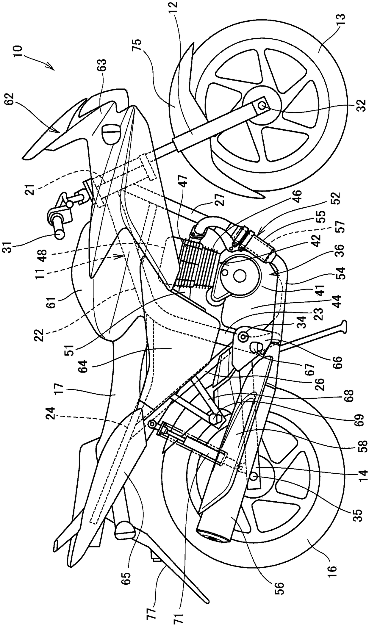
[0057] figure 1 It is a right side view of the motorcycle 10 provided with the catalytic converter supporting structure for the exhaust pipe of the first embodiment according to the present invention.

[0058] The motorcycle 10 has: a front wheel 13 supported on the front end of the vehicle body frame 11 via a front fork 12; a rear wheel 16 supported on the lower portion of the vehicle body frame 11 via a swing arm 14; Seat 17, it is installed on the top of vehicle body frame 11.

[0059] The motorcycle 10 is a saddle-ride type vehicle in which a passenger straddles a seat 17 .

[0060] The body frame 11 has a front riser 21 , a main frame 22 , a pair of left and right center frames 23 , a pair of left and right seat frames 24 , a pair of left and right sub frames 26 , and an under frame 27 .

[0061] The front stand pipe 21 constitutes a front end portion of the vehicle body frame 11 . The main frame 22 extends obliquely downward from the front stand pipe 21 rearward. The...

no. 2 approach

[0114] Figure 4 It is a vertical cross-sectional view showing the catalytic converter support structure of the exhaust pipe 100 according to the second embodiment. In the second embodiment, the same components as those in the first embodiment are denoted by the same reference numerals, and detailed description thereof will be omitted.

[0115] The exhaust pipe 100 is composed of a front exhaust pipe 101 and a rear exhaust pipe 102 which are divided into two parts.

[0116] The front exhaust pipe 101 has: from the cylinder head 47 (refer to figure 1 ) a front pipe portion 101a extending sideways; and a front enlarged diameter portion 101b integrally formed at the rear end portion of the front pipe portion 101a. The front enlarged diameter portion 101b is a portion enlarged in diameter from the front pipe portion 101a.

[0117] The rear exhaust pipe 102 has: from the muffler 56 (refer to figure 1 ) side extended rear pipe portion 102a; and rear enlarged diameter portion 102...

no. 3 approach

[0137] Figure 5 It is a vertical cross-sectional view showing the catalytic converter supporting structure of the exhaust pipe 110 according to the third embodiment. In the third embodiment, the same components as those in the first embodiment are denoted by the same reference numerals, and detailed description thereof will be omitted.

[0138] The exhaust pipe 110 is composed of a front exhaust pipe 111 and a rear exhaust pipe 112 which are divided into two parts.

[0139] The front exhaust pipe 111 has a flow from the cylinder head 47 (refer to figure 1 ) side extending front part pipe part 111a, and the front part enlarged diameter part 111b integrally formed in the rear end part of the front part pipe part 111a. The front enlarged diameter portion 111b is a portion enlarged in diameter from the front pipe portion 111a.

[0140] The rear exhaust pipe 112 has a slave muffler 56 (refer to figure 1 ) side extension of the rear pipe portion 112a, and the rear enlarged diam...


PUM


Abstract

The present invention provides a catalytic converter support structure for an exhaust pipe, which is a support structure effective for vibration of a vehicle body while ensuring ease of assembly and disassembly of the catalytic converter, and is also simple in structure and miniaturized. The intermediate portion of the exhaust pipe (54) that connects a cylinder head and a muffler is divided, and an outer cylinder (92) of a catalytic converter (57) using a catalyst to purify the exhaust gas is disposed across the end faces (81c, 82c) of the exhaust pipe (54). Further, one of the front exhaust pipe (81) and the rear exhaust pipe (82) (the front exhaust pipe (81)) before and after the end faces (81c, 82c) is provided with a front enlarged diameter portion (81b) that fixes one end of the outercylinder (92). Further, the other of the front exhaust pipe (81) and the rear exhaust pipe (82) (the rear exhaust pipe 82) is held at the other end of the outer cylinder (92). The outer cylinder (92)is detachably attached to cross the exhaust pipe (54), i.e., the front exhaust pipe (81) and the other rear exhaust pipe (82).

Description

technical field [0001] The invention relates to a catalytic converter support structure for an exhaust pipe. Background technique [0002] Conventionally, there is known a structure that ensures ease of detachment of the catalytic converter in the exhaust pipe (for example, refer to Patent Document 1). [0003] prior art literature [0004] Patent Document 1: Japanese Patent Laid-Open No. 2005-233053 [0005] In Patent Document 1, the cylindrical catalytic converter is supported by a cantilever, and since the metal honeycomb catalyst is heavy, there is a problem in the supporting structure with respect to the vibration of the vehicle body. In addition, the portion holding the catalytic converter has a triple structure including the catalytic converter, and the structure is complicated and assembly and disassembly are not easy, resulting in an enlarged arrangement space due to enlargement. Contents of the invention [0006] The object of the present invention is to provi...

Claims


Application Information

Patent Timeline
Patent Type & Authority Applications(China)
IPC IPC(8): F01N3/28F01N13/08F01N13/18
CPCF01N3/2882F01N13/08F01N13/18Y02A50/20
Inventor 久保俊博有贺洋介远藤武士政谷忠寿
Owner HONDA MOTOR CO LTD
Why Eureka
Try Eureka