Synchronization process and element for CHIRP spread spectrum communication system

A spread spectrum communication and synchronization signal technology, applied in electrical components, transmission systems, etc., can solve problems such as restricting applications, affecting the effect of synchronization, errors, etc., to reduce computational complexity and improve synchronization accuracy.

Inactive Publication Date: 2008-11-12
UNIV OF ELECTRONICS SCI & TECH OF CHINA
View PDF0 Cites 10 Cited by
  • Summary
  • Abstract
  • Description
  • Claims
  • Application Information

AI Technical Summary

Problems solved by technology

The first problem is that when there is a time difference between the receiver’s local reference signal and the received signal, the two frequency components in the product signal that are multiplied by the two correspond to different frequency bands of the channel, so the strength of the two will be affected by channel fading , which will lead to errors in judging the frequency component of the maximum intensity, thus affecting the synchronization effect
The second problem is that when estimating the frequency of the strongest frequency component, in order to obtain sufficient estimation accuracy, there need to be enough sampling values, which will lead to a large amount of calculation for frequency estimation
These two issues limit the application of this method

Method used


Image

  • Synchronization process and element for CHIRP spread spectrum communication system
  • Synchronization process and element for CHIRP spread spectrum communication system

Examples


Embodiment Construction

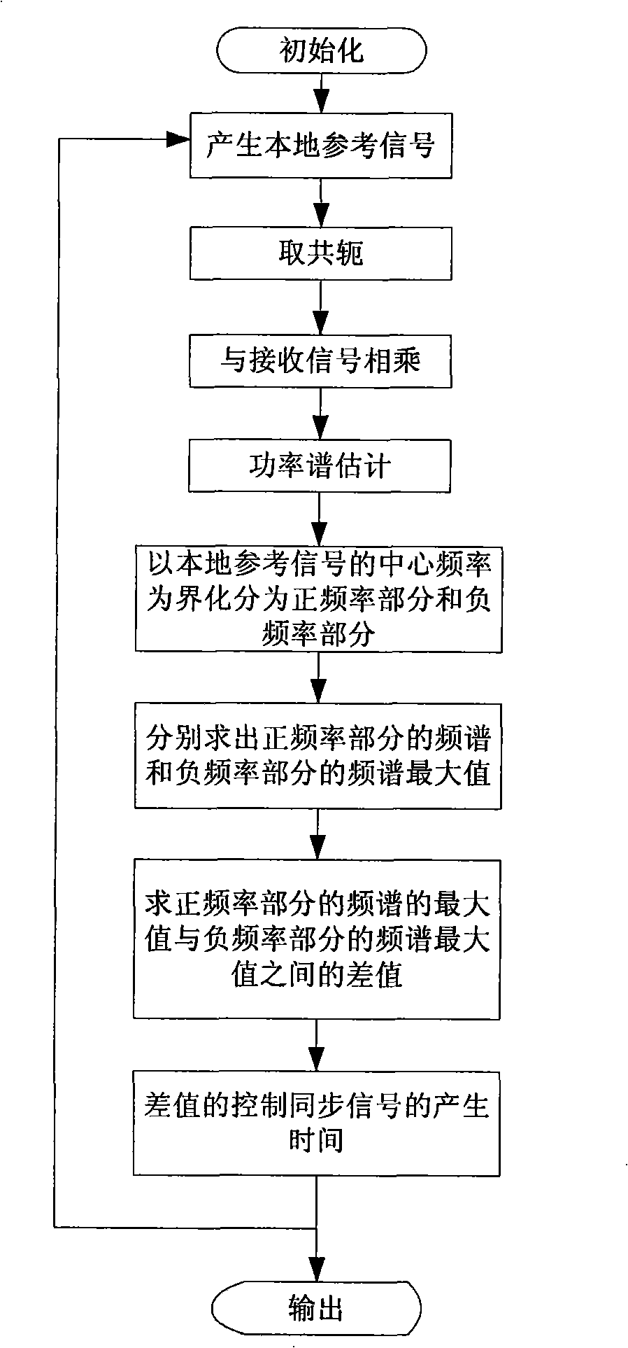
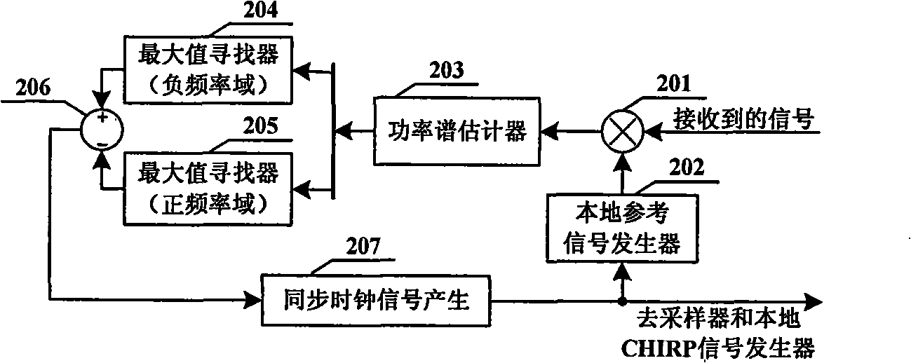
[0016] The specific embodiment of the method of the present invention is as figure 1 As shown, the specific steps are described as follows:

[0017] Step 1: Initially set up a synchronous clock signal.

[0018] Step 2: Generate a local reference signal under the control of the initial clock signal or the synchronous clock signal generated in step 7. The center frequency of the local reference signal is the same as the center frequency of the CHIRP signal generated by the transmitter, but the frequency sweep of the local reference signal The range and sweep time are twice as large as the sweep range and sweep time of the CHIRP signal generated by the transmitter; (through the processing of this step, the influence of the channel is removed)

[0019] Step 3: The local reference signal generated in step 2 is multiplied by the received signal after taking the conjugate;

[0020] Step 4: Estimate the power spectrum of the product of step 3;

[0021] Step 5: find out the intensit...


PUM


Abstract

The invention relates to a novel synchronous method and component with low complexity used in the CHIRP spread spectrum communication system, avoiding the judgment mistakes on the frequency component with the maximum intensity when the time difference exists between the local referenced signals and the receiving signals of a receiver. The method for the invention includes the following steps: a receiving terminal generates a local referenced signal after triggered by a synchronous signal, multiplies a received CHIRP signal by the local referenced signal and then calculates the intensity difference between two frequency components in the product with the maximum intensity; then the receiving terminal generates the synchronous signals under the control of the intensity difference and the synchronous signals triggers the generation of the local referenced signal so as to gradually reduce the time difference between the received signal and the local referenced signal until the time difference becomes zero, thus achieving the synchronization of the received signals. Compared with the existing method, the method of the invention improves the synchronous accuracy as well as reduces the computational complexity.

Description

technical field [0001] The invention relates to a synchronization method applied to a Chirp spread spectrum communication system in wireless communication, belonging to the synchronization field of communication systems. Background technique [0002] In recent years, the chirp (Chirp) spread spectrum communication technology using continuous carrier has gradually attracted people's attention. IEEE802.15.4a adopted Chirp chirp spread spectrum (CSS for short) in March 2007 as one of its standard physical layer technologies. Synchronization technology is a key technology in Chirp spread spectrum communication system, and the accuracy of synchronization will seriously affect the communication performance of the whole system. There are two types of synchronization technologies currently proposed, one is the method of using matched filtering, that is, a pair of matched filters are used at both ends of the transmitting and receiving end, so that the receiving end can directly obta...

Claims


Application Information

Patent Timeline
Patent Type & Authority Applications(China)
IPC IPC(8): H04B1/69H04B1/7073
Inventor 刘皓孙嘉
Owner UNIV OF ELECTRONICS SCI & TECH OF CHINA
Why Eureka
Try Eureka