
Wireless synchronization method and wireless synchronization system

A synchronization system and wireless technology, applied in radio wave measurement systems, synchronization devices, wireless communications, etc., can solve problems such as affecting positioning accuracy, deterioration of synchronization accuracy, and failure of synchronization accuracy to meet expected requirements.

Active Publication Date: 2015-11-25
ZTE CORP
View PDF4 Cites 0 Cited by
  • Summary
  • Abstract
  • Description
  • Claims
  • Application Information

AI Technical Summary

Problems solved by technology

Each positioning signal station of the ground wireless positioning system is arranged close to the ground, which is easily blocked and reflected by various buildings on the ground. Therefore, if a unified control station is used to complete the synchronization between each positioning signal station, the complex conditions on the ground It will make the synchronization accuracy worse and eventually affect the positioning accuracy
[0006] In the prior art, the synchronization accuracy between nodes often fails to meet the expected requirements due to the processing of reflection, multipath, etc., so if the positioning accuracy needs to be improved, it is necessary to improve the synchronization accuracy between the nodes for positioning processing a problem solved

Method used


Image

  • Wireless synchronization method and wireless synchronization system
  • Wireless synchronization method and wireless synchronization system
  • Wireless synchronization method and wireless synchronization system

Examples


Embodiment 1

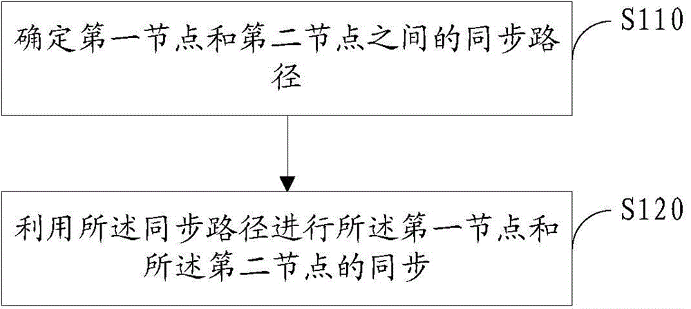
[0124] Such as figure 1 As shown, this embodiment provides a wireless synchronization method, the method comprising:

[0125] Step S110: determining a synchronization path between the first node and the second node;

[0126] Step S120: using the synchronization path to synchronize the first node and the second node;

[0127] Wherein, the synchronization path is composed of one or more visible paths;

[0128] The visible path is a direct path connecting two mutually visible nodes.

[0129] In the prior art, the first node and the second node are directly synchronized through wireless transmission technology; in the process of synchronizing the signal, it may be affected by terrain factors such as buildings and high ground, which may cause the synchronization signal to be reflected and multiplied during transmission. path and other phenomena, thereby causing the delayed arrival of the synchronization signal, and then resulting in insufficient synchronization accuracy; and in ...

Embodiment 2

[0226] Such as Figure 8 As shown, this embodiment provides a wireless synchronization system, and the wireless synchronization system includes:

[0227] a determining unit 110, configured to determine a synchronization path between the first node and the second node;

[0228] a synchronization unit 120, configured to use the synchronization path to synchronize the first node and the second node;

[0229] Wherein, the synchronization path is composed of one or more visible paths;

[0230] The visible path is a direct path connecting two mutually visible nodes.

[0231] In a specific implementation process, the specific structure of the determination unit 110 may be a processor and a storage medium; executable instructions of the processor are stored on the storage medium; The structure reads and runs the executable instruction to determine the synchronization path between the first node and the second node. The processor described in this embodiment may be an electronic co...


PUM


Abstract

Disclosed are a wireless synchronization method and a wireless synchronization system. The method comprises: determining a synchronization path between a first node and a second node (S110); and using the synchronization path to synchronize the first node and the second node (S120), wherein the synchronization path is composed of one or more segments of visible paths, and the visible path is a direct path which connects two nodes visible to each other. Further disclosed is a computer storage medium.

Description

technical field [0001] The invention relates to synchronization technology in the communication field, in particular to a wireless synchronization method and a wireless synchronization system. Background technique [0002] With the continuous development of communication technology and electronic information technology, more and more attention has been paid to positioning technology, and the demand for high-precision positioning is becoming more and more obvious, especially the demand for high-precision positioning and indoor positioning. [0003] Due to signal loss and other reasons, the Global Positioning System (GPS) positioning technology weakens the indoor signal, making it impossible for the positioning terminal to receive enough satellites; due to the large positioning error of the cellular network system, it cannot be achieved either outdoors or indoors. Sufficient accuracy cannot meet the needs of wireless positioning. [0004] Improving the accuracy of wireless po...

Claims


Application Information

Patent Timeline
Patent Type & Authority Applications(China)
IPC IPC(8): H04W56/00
CPCG01S1/024H04W56/001H04W56/00
Inventor 陈诗军胡留军郁光辉陆海涛
Owner ZTE CORP
Learn More