Method and device for achieving clock time synchronization

A clock time, clock technology, applied in the field of Ethernet, can solve the problems of inconsistency and error of two-way delay

Active Publication Date: 2014-06-25
RAISECOM TECH
View PDF4 Cites 25 Cited by
  • Summary
  • Abstract
  • Description
  • Claims
  • Application Information

AI Technical Summary

Problems solved by technology

[0009] It can be seen from the above description that the above calculation of the path delay and phase difference is based on the delay from the Master Clock to the Slave Clock and the delay from the Slave Clock to the Master Clock. Changes in the environment will bring errors, which

Method used


Image

  • Method and device for achieving clock time synchronization
  • Method and device for achieving clock time synchronization
  • Method and device for achieving clock time synchronization

Examples


Embodiment 1

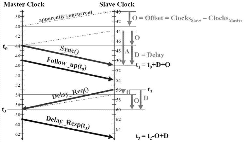
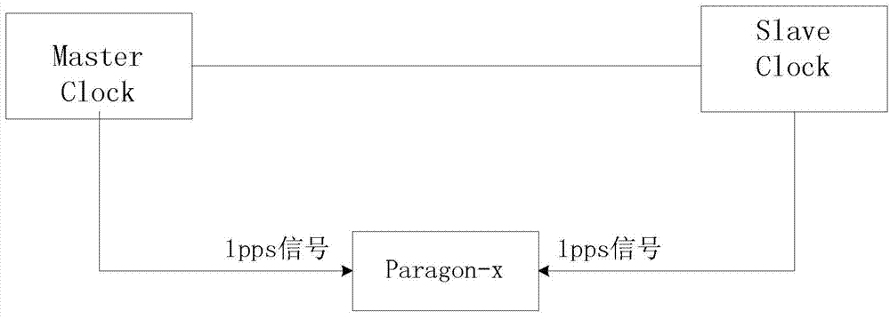
[0056] The inventor realizes the purpose of this application by using the Kalman filter algorithm, which is based on the statistical law of noise and estimates the current state of time synchronization between Master Clock and Slave Clock according to the principle of minimum estimation error, so as to be used for clock synchronization adjustment. It depends on the test model such as figure 2 shown. Specifically, the Kalman filter algorithm uses the state equation to determine the time synchronization state of the Master Clock and Slave Clock (see equation (1)) and the measurement equation to determine the measurement vector of the time synchronization state of the Master Clock and Slave Clock (see equation (2)) to realise:

[0057] X(k)=F(k,k-1)X(k-1)+W(k) (1)

[0058] Y(k)=HX(k-1)+V(k) (2)

[0059] Among them, X(k) is the state vector;

[0060] Y(k) is the measurement vector of the state;

[0061] F(k, k-1) is the transition matrix from the k-1th time synchronization s...

Embodiment 2

[0104] This embodiment provides a device for implementing clock time synchronization, which estimates the current time synchronization state of the Master Clock and Slave Clock based on the statistical law of noise and the principle of minimum estimation error, so as to be used for clock synchronization adjustment. The device includes at least the following modules:

[0105] The first module uses the difference between the sending and receiving timestamps of the synchronization message packet and the response message packet in the PTP message packet as the observed value to estimate the clock deviation, clock frequency deviation and aging rate, and obtain the phase difference between the master and slave clocks ;

[0106] In another embodiment, with the same basic structure of the above-mentioned device, the first module uses the difference between the synchronization message packet in the PTP message packet and the sending and receiving time stamp of the response message pack...


PUM


Abstract

The invention discloses a method and device for achieving clock time synchronization, and relates to the Ethernet technology. The method comprises the steps of estimating the clock jitter and the clock frequency deviation with the difference of sending and receiving timestamp of a synchronous message packet and the difference of sending and receiving timestamp of a response message packet in a precision time protocol (PTP) message packet as observed values respectively to obtain the phase difference of a master clock and a slave clock, and carrying out the synchronization adjustment on the slave clock according to the estimated phase difference. The invention further discloses the device for achieving the clock time synchronization. According to the technical scheme, the state quantity is obtained by calculating measuring values respectively based on the kalman filtering algorithm and the combination (O+D and O-D) of the phase difference and the path delay, the estimated value for the clock synchronization phase difference is obviously far more superior to the estimated value, worked out through the single measuring value of the phase difference serving as the state value, for the clock synchronization phase difference , the phase difference can be reflected better and the synchronous precision between the master clock and the slave clock is greatly improved.

Description

technical field [0001] The present invention relates to Ethernet technology, in particular to a method and device for realizing clock time synchronization. Background technique [0002] With the development of science and technology, people have higher and higher requirements for time accuracy, and the computer and network industries are all committed to solving the problem of insufficient timing synchronization capability of Ethernet. The Network Precision Clock Synchronization Committee has passed the IEEE1588 standard (referred to as PTP, Precision Time Protocol, precision clock synchronization protocol). IEEE1588 is based on Ethernet and distributed system applications, and its time synchronization accuracy can reach sub-microsecond level. The basic principles are as follows: figure 1 shown. figure 1 Among them, the Master Clock is the main clock, the Slave Clock is the slave clock, O is the phase difference Offset between the Slave Clock and the Master Clock, and D is ...

Claims


Application Information

Patent Timeline
IPC IPC(8): H04L7/00
Inventor 韩一强安伟
Owner RAISECOM TECH
Why Eureka
Try Eureka