Cleaning device for an iron

A technology for cleaning devices and irons, applied in hand irons, washing devices, applications, etc., can solve the problems of wear and unfavorable mechanical stability of steam irons

Inactive Publication Date: 2008-11-12
BSH BOSCH & SIEMENS HAUSGERAETE GMBH
View PDF1 Cites 0 Cited by
  • Summary
  • Abstract
  • Description
  • Claims
  • Application Information

AI Technical Summary

Problems solved by technology

This also has a very negative effect on the wear and mechanical stability of the steam iron

Method used


Image

  • Cleaning device for an iron
  • Cleaning device for an iron
  • Cleaning device for an iron

Examples


Embodiment Construction

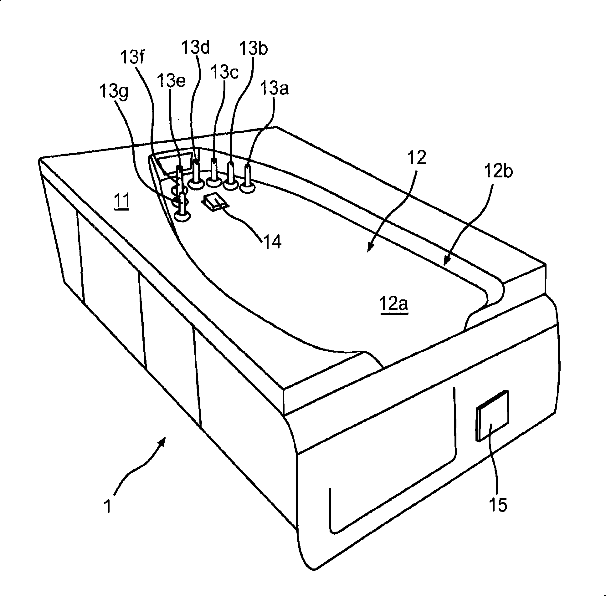
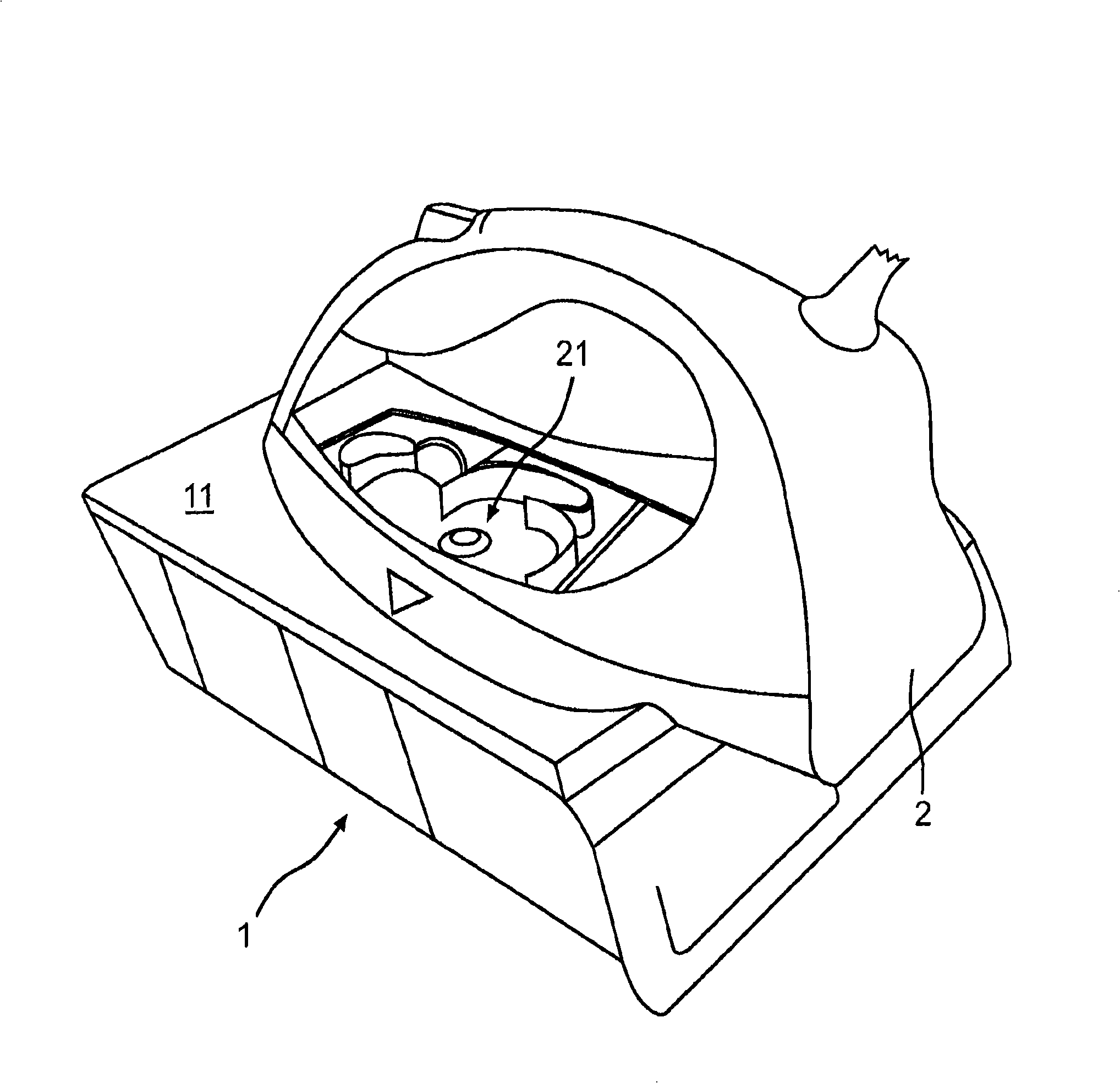
[0024] exist figure 1 A cleaning device 1 for a steam iron is shown in a perspective view. The cleaning unit is designed for cleaning steam irons 2 ( Figure 4 ), which has an iron sole 22, wherein at least two steam outlets 23a to 23g are formed in this iron sole 22, from which steam can be discharged onto the ironing object. The steam outlets 23a to 23g lead to the steam chamber 21 ( figure 2 ) or are respectively connected with the steam chamber 21 of the steam iron 2 through steam passages.

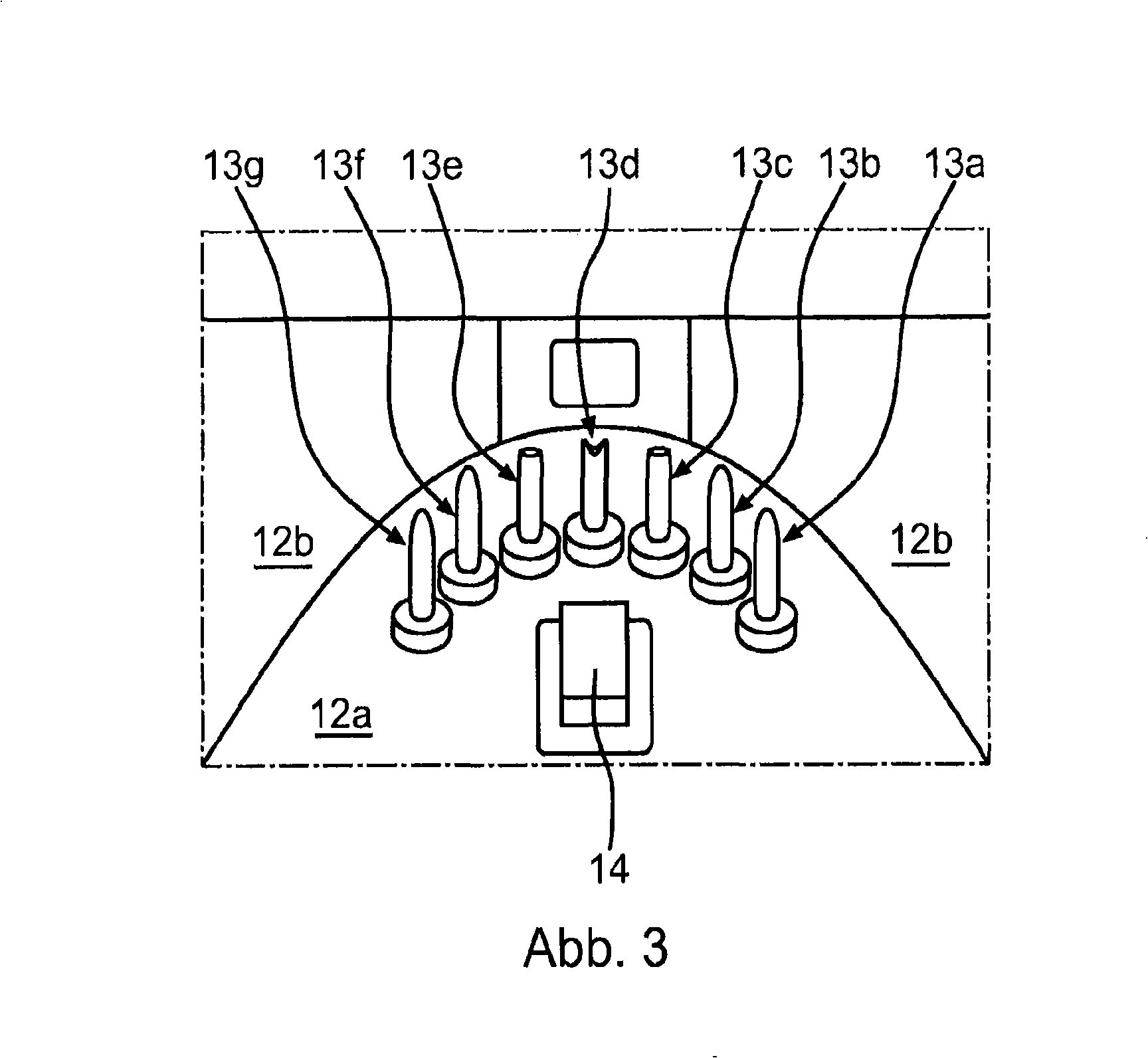
[0025] as in figure 1 As can be seen in the figure, the cleaning device 1 has a top surface 11 in which a recess 12 is formed. like figure 1As shown, the recess 12 has a base region 12a and a wall region 12b. The depression 12 is formed in such a way that it at least partially corresponds to the shape of the sole of the steam iron.

[0026] In the exemplary embodiment, the cleaning device 1 has a plurality of cleaning elements and closure elements. The closure elements are in...


PUM


Abstract

The invention relates to a cleaning device (1) for a steam iron (2) comprising a base plate (22) with at least two steam outlets (23a to 23g), the steam outlets leading to a steam compartment (21) of the steam iron. The cleaning device is designed as a separate system, having a first cleaning element (13c, 13d, 13e) and at least a second cleaning element for cleaning at least the steam compartment. The first cleaning element can be introduced into a first steam outlet and the second cleaning element can be introduced into a second steam outlet.

Description

technical field [0001] The invention relates to a cleaning device for a steam iron, wherein the steam iron has an iron sole with at least two steam outlets and the steam outlets lead into a steam chamber of the steam iron. Background technique [0002] A steam iron is known from German laid-open document DE 32 04 796 A1, in which a reservoir for the water to be evaporated can be replaced by a water pump as a cleaning device. The reservoir and the water pump can be supported on the soleplate or sole of the steam iron and can be fastened to the handle of the steam iron. The water pump presses water for cleaning through the steam chamber formed in the sole of the iron and through the steam channels formed in the sole of the iron. The water flows out of the steam outlet, which is formed in the sole of the iron and opens into the steam duct or steam chamber. However, the cleaning of steam irons, in particular of the steam chamber, can only be carried out very inadequately. In ...

Claims


Application Information

Patent Timeline
Patent Type & Authority Applications(China)
IPC IPC(8): D06F79/02D06F75/38D06F75/18
CPCD06F79/02D06F75/18D06F75/38
Inventor C·艾班多茨鲁茨德奥森达
Owner BSH BOSCH & SIEMENS HAUSGERAETE GMBH
Why Eureka
Try Eureka