Thermoelectric generator

a generator and thermoelectric technology, applied in the field of micro electromechanical systems, can solve the problems of reducing and the known silicon-based thermoelectric generator is not satisfactory for some modern technological specifications, so as to reduce the mechanical stability of the conventional silicon-based thermoelectric generator

Pending Publication Date: 2021-08-05
STMICROELECTRONICS SRL
View PDF4 Cites 0 Cited by
  • Summary
  • Abstract
  • Description
  • Claims
  • Application Information

AI Technical Summary

Benefits of technology

[0012]In fact, the presence of a cavity reduces the mechanical stability of the conventional silicon-based thermoelectric generators.

Problems solved by technology

Known silicon-based thermoelectric generators are not satisfactory for some modern technological specifications.
In fact, the presence of a cavity reduces the mechanical stability of the conventional silicon-based thermoelectric generators.

Method used


Image

  • Thermoelectric generator
  • Thermoelectric generator
  • Thermoelectric generator

Examples


Embodiment Construction

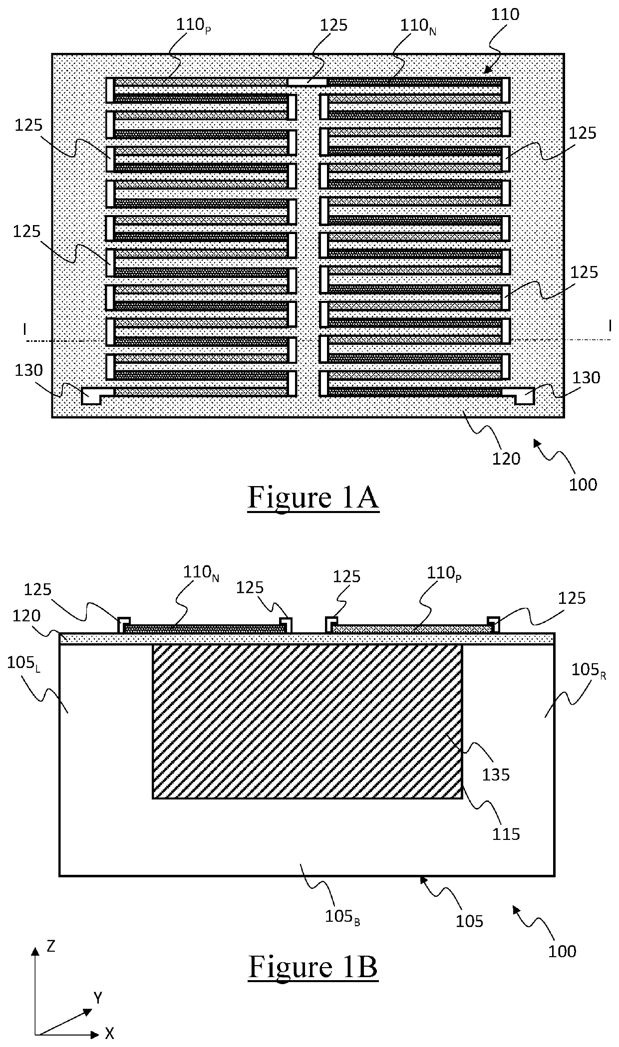
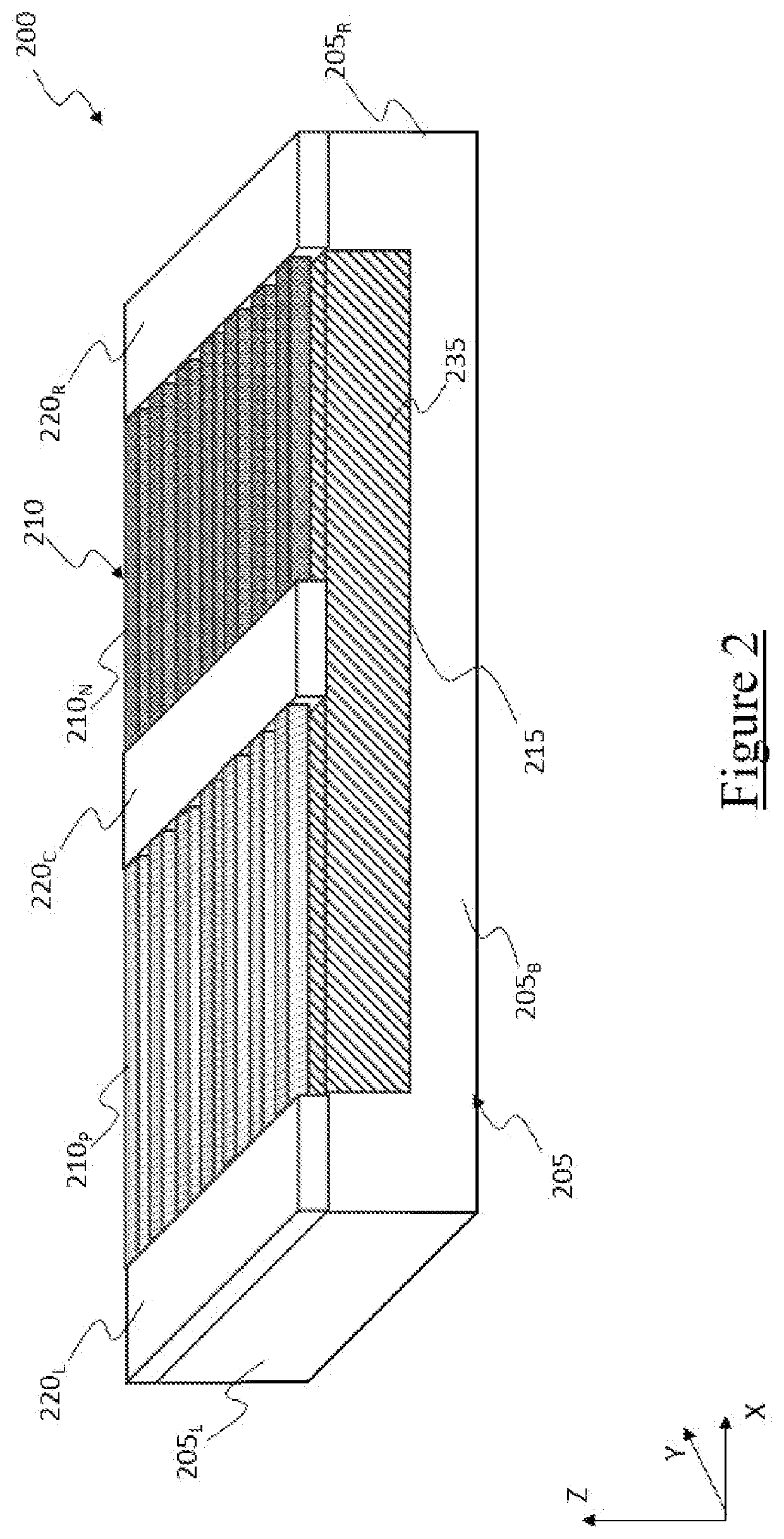
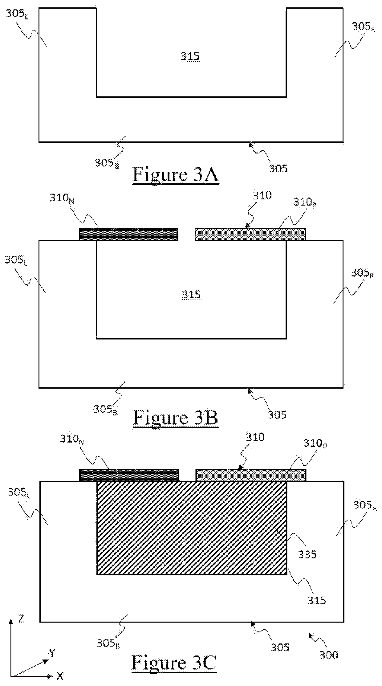
[0028]With reference to the drawings, they show simplified representations of thermoelectric generators according to embodiments of the present disclosure.

[0029]In the following, when one or more features are introduced by the wording “according to an embodiment”, they are to be construed as features additional or alternative to any feature(s) previously introduced, unless otherwise indicated and / or unless an incompatibility between combinations of features that would be immediately apparent to the person skilled in the art.

[0030]In the following, directional terminology (for example, upper, lower, lateral, central, longitudinal, transverse and vertical) associated with the thermoelectric generators and components thereof will be used only in connection with their orientation in the figures, and is not indicative of any specific orientation of use thereof. In this respect, a reference system is illustrated in the figures, the reference system being identified by three orthogonal dir...


PUM


Abstract

A thermoelectric generator includes a substrate and one or more thermoelectric elements on the substrate and each configured to convert a thermal drop across the thermoelectric elements into an electric potential by Seebeck effect. The thermoelectric generator includes a cavity between the substrate and the thermoelectric elements. The thermoelectric generator includes, within the cavity, a support structure for supporting the thermoelectric elements. The support structure has a thermal conductivity lower than a thermal conductivity of the substrate.

Description

BACKGROUNDTechnical Field[0001]The present disclosure generally relates to the field of MEMS (Micro Electro-Mechanical Systems) devices. Particularly, the present disclosure generally relates to the field of thermoelectric generators, i.e., devices configured to directly convert a thermal energy (particularly, a temperature gradient or thermal drop) into electric energy (particularly, an electric potential) by Seebeck effect.Description of the Related Art[0002]Direct conversion of thermal energy into electric energy by Seebeck effect is a promising approach for harvesting energy from heat sources, particularly from heat sources that otherwise would not be exploited (such as waste heat of industrial plants, residual heat of car engines, low temperature thermal sources), e.g., due to the reduced temperature gradients that would be attained.[0003]Tellurium-based thermoelectric generators are known.[0004]Tellurium compounds, such as bismuth telluride (Bi2Te3), exhibit good Seebeck coeff...

Claims


Application Information

Patent Timeline
Patent Type & Authority Applications(United States)
IPC IPC(8): H01L35/32H01L35/34
CPCH01L35/32H01L35/34H10N10/855H10N10/17H10N10/01
Inventor FERRARI, PAOLOVILLA, FLAVIO FRANCESCOZANOTTI, LUCANOMELLINI, ANDREASEGHIZZI, LUCA
Owner STMICROELECTRONICS SRL
Why Eureka
Try Eureka