Electric connector

A technology of connectors and paired connectors, which is applied in the direction of connection, two-part connection devices, circuits, etc., can solve the problems of non-reduced distance, increased distance, and reduced area, and achieve the effect of reducing the installation area

Inactive Publication Date: 2008-11-12
MOLEX INC
View PDF1 Cites 5 Cited by
  • Summary
  • Abstract
  • Description
  • Claims
  • Application Information

AI Technical Summary

Problems solved by technology

However, because of the soldering precision and technical limitations of the circuit board, the distance between the through holes 306 and 307 cannot be reduced to a preset distance or even smaller
Therefore, the distance between the vertically downward portions of the terminals 302 and 303 cannot be reduced, and the distance measured from the vertically downward portion of the terminal 303 to the opening of the connector housing 304 increases, which makes the installation of the board mount connector The length of the region ( Figure 5 lateral dimension) and its area cannot be reduced

Method used


Image

  • Electric connector
  • Electric connector
  • Electric connector

Examples


Embodiment Construction

[0020] Embodiments of the present invention will be described in detail below with reference to the accompanying drawings.

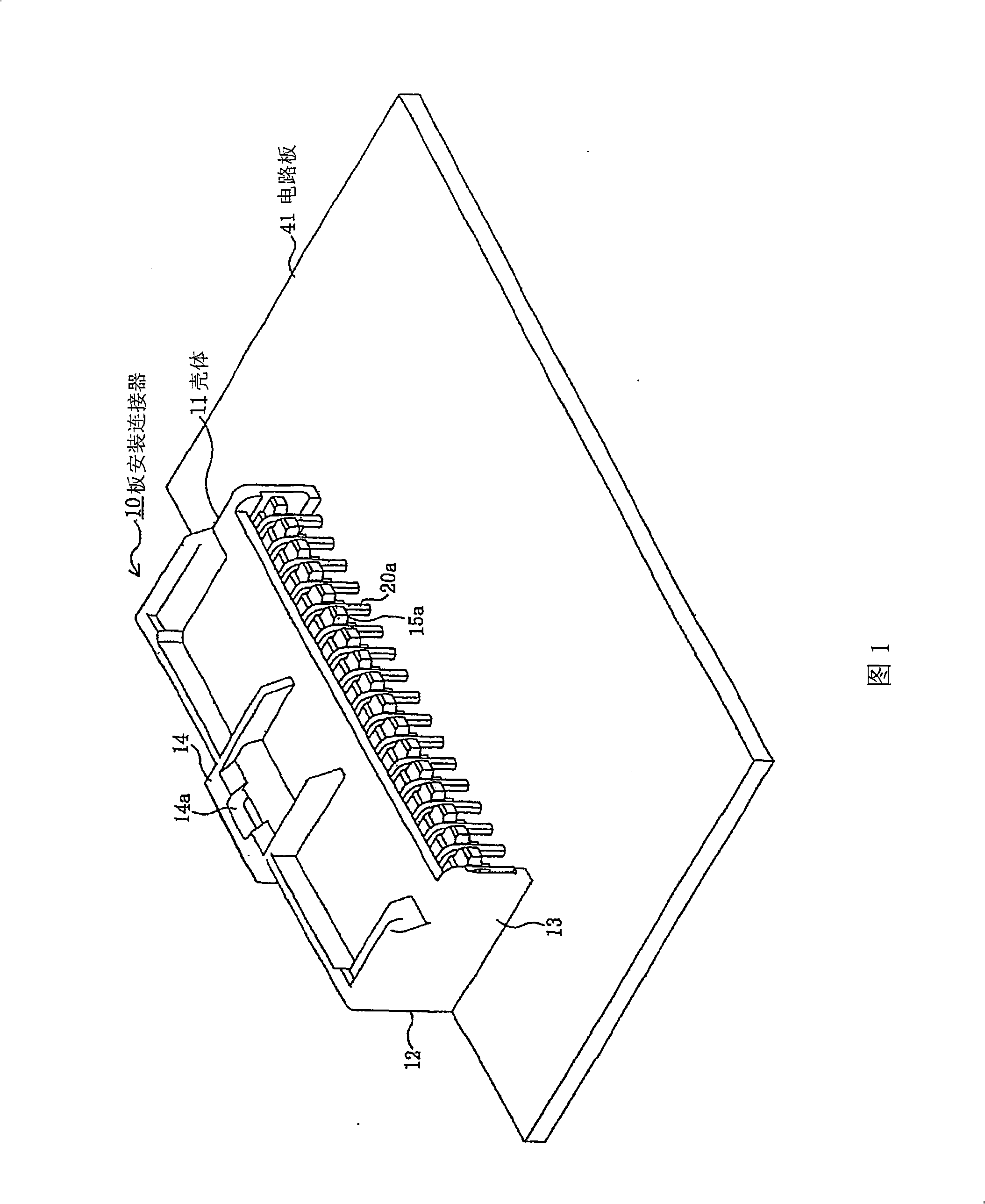
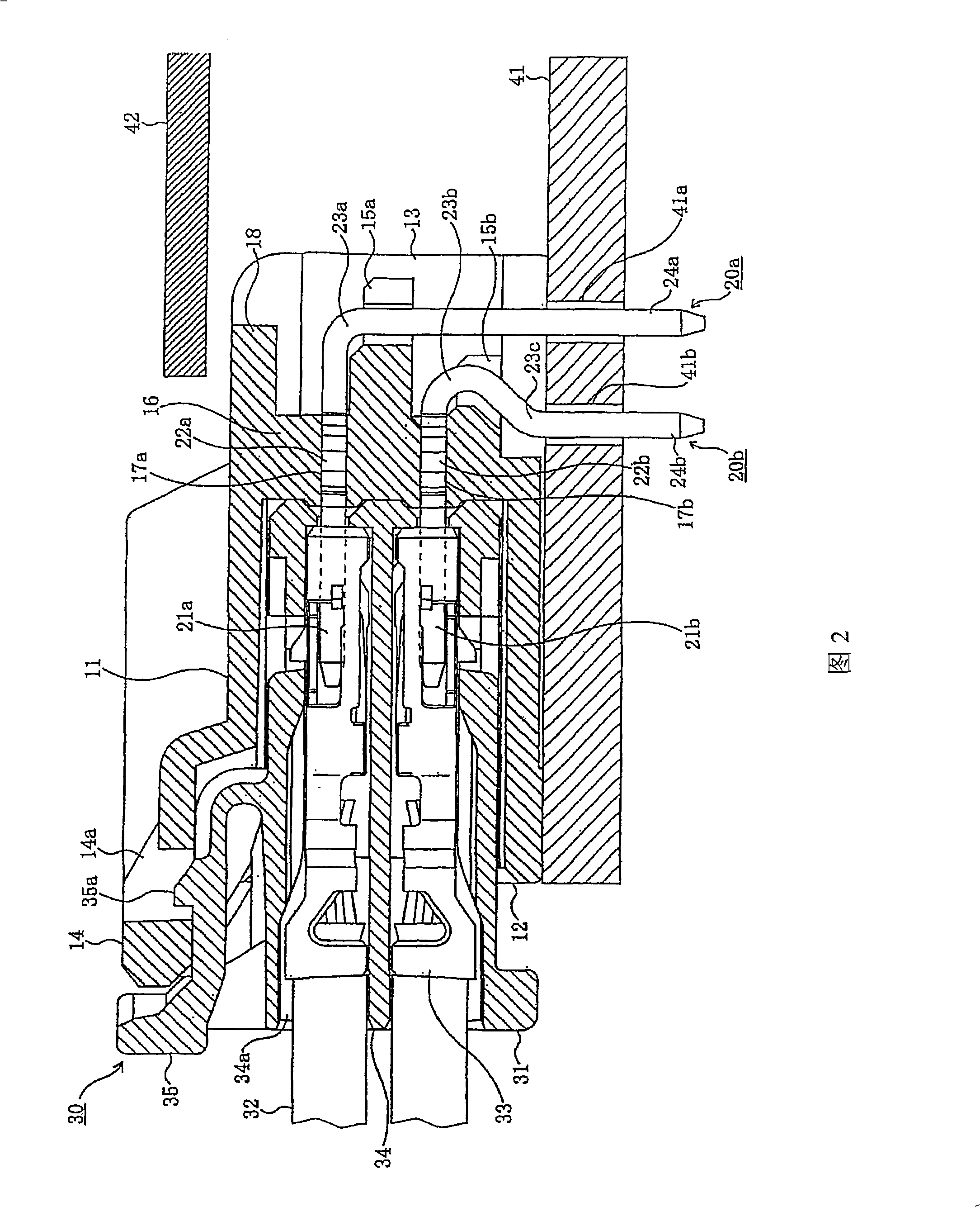
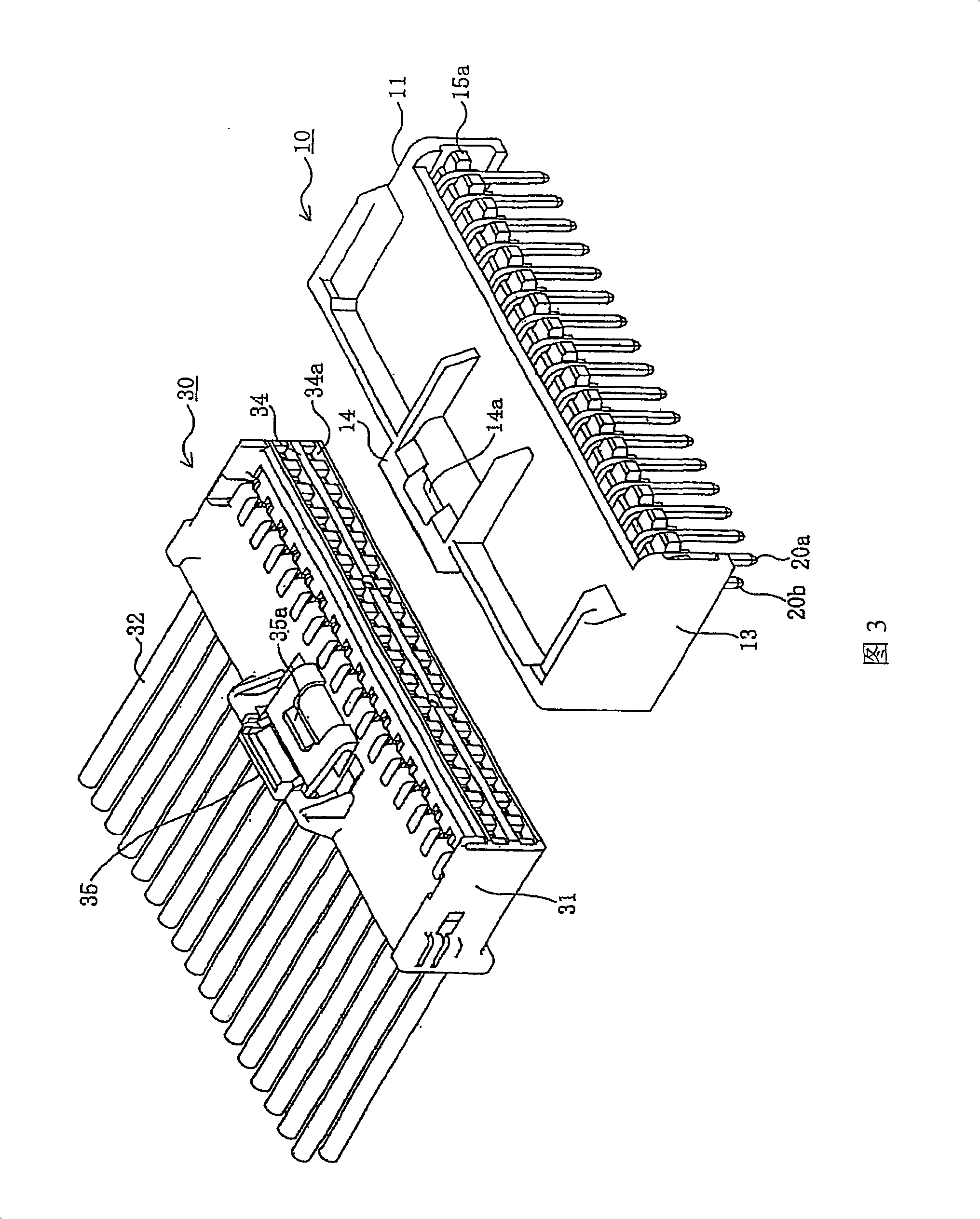
[0021] 1 is a perspective view of a board mount connector according to an embodiment of the present invention; FIG. 2 is a cross-sectional view of the board mount connector of the above embodiment, showing the state after it is mated with a mating connector.

[0022] Referring to FIG. 1 , the board mount connector 10 according to the present embodiment is mounted on a board (circuit board) 41, and is mated with a mating connector 30 to establish a connection between the circuit board 41 and an instrument connected to the mating connector 30. electrical connection. In this embodiment, the mating connector 30 is not only used for connecting cables, as shown in FIG. Flexible cables such as flexible flat cables (FFC) and flexible printed circuits (FPC) and the like. In the present embodiment, words used to express directions, such as up, down, left, right,...


PUM


Abstract

A board mount connector (10) includes a connector body configured to be mated with a counterpart connector (30) and a plurality of conductive terminals (20a, 20b) projecting from the connector body (11). Each of the terminals includes a contact portion (21a, 21b) configured to contact a corresponding terminal (33) of the counterpart connector (30), a leg portion (24a, 24b) configured to be inserted into a corresponding connection hole (41a, 41b) and soldered thereto, and a bent portion (23a, 23b) which connects the arm portion (21a, 21b) and the leg portion (24a, 24b). The bent portion (23a) of each longer terminal (20a) forms an arc with a center angle of 90 degrees and the bent portion (23b) of each shorter terminal (20b) forms an arc with a center angle greater than 90 degrees. The contact portion (21a, 21b) of the terminals extends parallel to the circuit board (41), and the leg portion (24a, 24b) of the terminals extends perpendicular to the circuit board (41).

Description

technical field [0001] The present invention relates to board mount connectors. Background technique [0002] A board mount connector is known which is generally mounted on a board, such as a printed circuit board, to connect another circuit or the like (refer to, for example, Japanese Patent Application Laid-Open No. 2004-192871). Such a board mount connector includes a connector body and a plurality of L-shaped terminals protruding rearward away from the connector body. [0003] Figure 5 A perspective view of an existing board mount connector is shown. [0004] Figure 5 The illustrated board mount connector includes terminals 302 and 303, both of which are made of conductive material (such as metal); the board mount connector also includes a box-shaped connector housing 304, which The case is made of an insulating material such as synthetic resin and supports the terminals 302 and 303 . The board mount connector is a so-called plug connector, and a socket connector co...

Claims


Application Information

Patent Timeline
Patent Type & Authority Applications(China)
IPC IPC(8): H01R12/18
CPCH01R23/7073H01R12/724H01R12/72
Inventor 江里口学浅川和重
Owner MOLEX INC
Why Eureka
Try Eureka