[0021] Reference will now be made in detail to the embodiments of the present invention, examples of which are illustrated in the accompanying drawings.
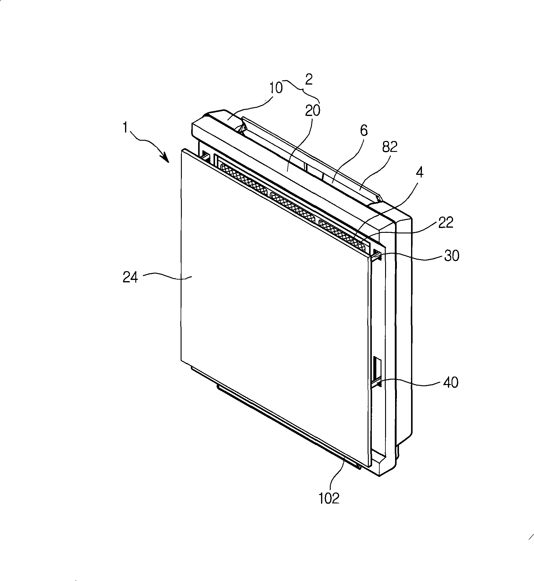
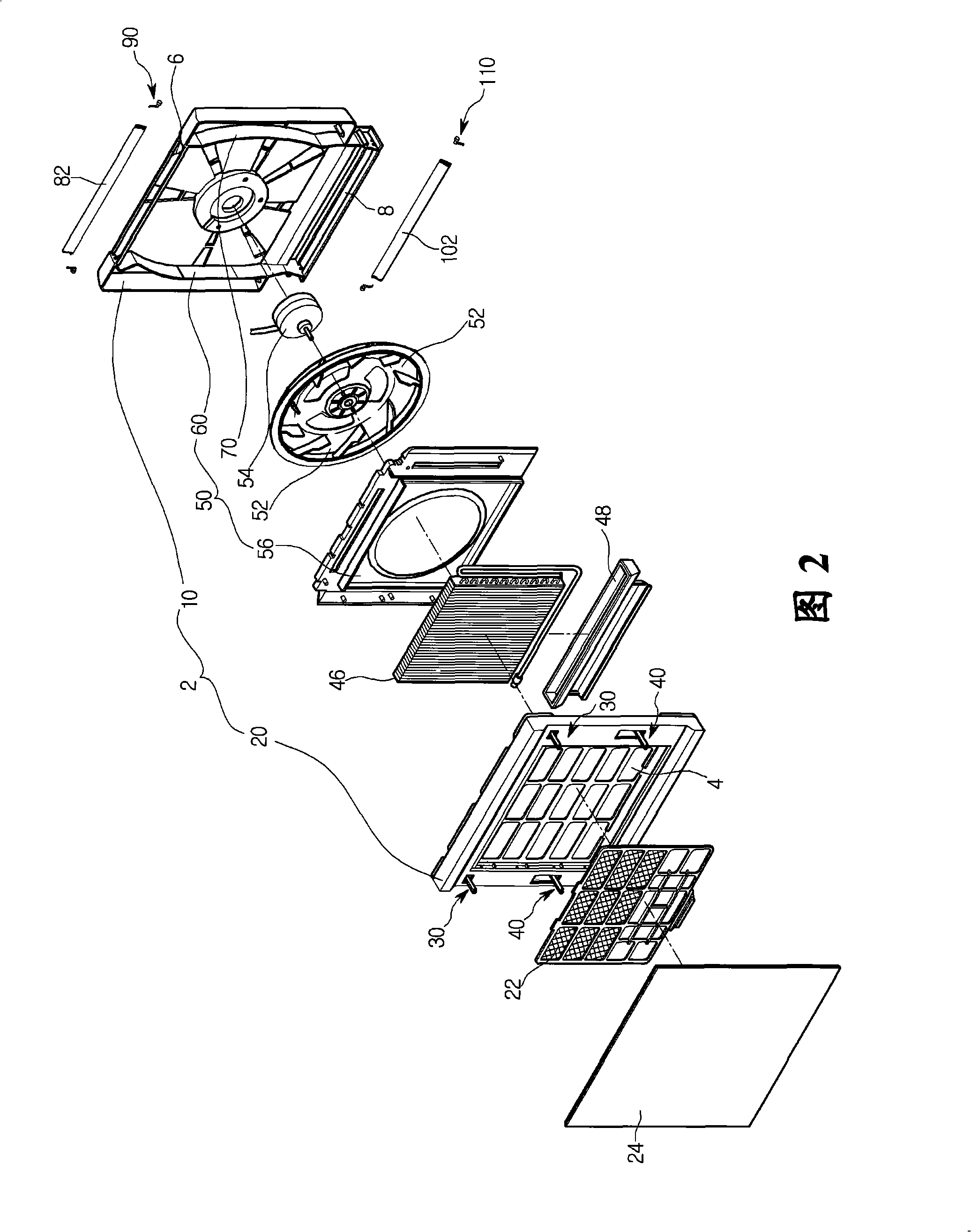
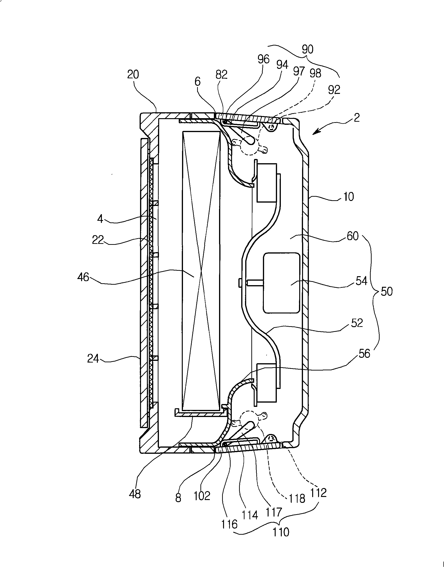
[0022] figure 1 is a perspective view of the air conditioner according to the present embodiment, and FIG. 2 is an exploded perspective view of the air conditioner according to the present embodiment, image 3 is a sectional view of the air conditioner when it is not in operation, Figure 4 is a cross-sectional view of the air conditioner in top discharge mode, and Figure 5 is a sectional view of the air conditioner in the down discharge mode.
[0023] Figure 1 to Figure 5 The indoor unit of the wall-mounted air conditioner is shown, and the following description will be limited to the indoor unit of the air conditioner.
[0024] refer to Figure 1 to Figure 5 , the indoor unit 1 of the air conditioner according to the present embodiment includes a main body 2 that constitutes the exterior of the indoor unit 1 .
[0025] The air inlet 4 is defined in the front of the main body 2 , the upper air outlet 6 is defined in the upper surface of the main body 2 , and the lower air outlet 8 is defined in the lower surface of the main body 2 .
[0026] Specifically, the main body 2 includes: a rear frame 10 ; and a front frame 20 coupled to the front of the rear frame 10 .
[0027] The air inlet 4 is defined in the front frame 20 . In addition, a filter 22 for filtering air is provided in front of the front frame 20 .
[0028] The front panel 24 is coupled to the front of the front frame 20 to open and close the air inlet 4 . The front plate 24 may be rotatably coupled to the front frame 20, or may be coupled to the front frame 20 so as to be able to move forward and rearward.
[0029] Panel driving units 30 and 40 for driving the front panel 24 are provided on the front frame 20 . The panel driving units 30 and 40 include an upper driving unit 30 connected to an upper end portion of the front panel 24 and a lower driving unit 40 connected to a lower end portion of the front panel 24 .
[0030] The upper driving unit 30 and the lower driving unit 40 can operate independently. That is, the upper driving unit 30 and the lower driving unit 40 may operate together, or only one.
[0031] Therefore, when the upper driving unit 30 and the lower driving unit 40 are simultaneously operated together, the front plate 24 can move horizontally forward and rearward relative to the front frame 20 . On the contrary, when only one of the upper driving unit 30 and the lower driving unit 40 is operated, the front plate 24 can be rotated relative to the main body 2 .
[0032] The upper driving unit 30 is connected to the upper left side and the upper right side of the front panel 24 , and the lower driving unit 40 is connected to the lower left side and the lower right side of the front panel 24 .
[0033] Inside the main body 2 are provided: a blower 50 ; a heat exchanger 46 that exchanges heat between the air drawn into the main body 2 and the refrigerant inside the heat exchanger 46 ; of condensate.
[0034] Specifically, the blower 50 includes: a fan 52; a fan motor 54 for rotating the fan 52; and an air vent 56 provided in front of the fan 52 for guiding air intake.
[0035] As an example, the fan 52 may be a centrifugal fan. The vent 56 is provided between the heat exchanger 46 and the fan 52 .
[0036] The blower 50 also includes channel guides 60 and 70 that form channels for blowing air through the fan 52 . Passage guides 60 and 70 enclose portions of the perimeter of fan 52 . The channel guides 60 and 70 include a left channel guide 60 and a right channel guide 70 separated from the left channel guide 60 . The left and right channel guides 60 and 70 may be integrally formed with the rear frame 10, or may be formed separately from the rear frame 10, and then combined with the rear frame 10 by means of adhesive members or the like. The channel guides 60 and 70 will be described later with reference to the drawings. Here, the left channel guide 60 may be referred to as a first channel guide, and the right channel guide 70 may be referred to as a second channel guide.
[0037] The upper vane 82 that opens and closes the upper air outlet 6 and the lower vane 102 that opens and closes the lower air outlet 8 are provided on the main body 2 . Vanes 82 and 102 control the direction of air exhausted through air outlets 6 and 8, respectively.
[0038] Blades 82 and 102 are operable independently of each other. Therefore, only one of the upper air outlet 6 and the lower air outlet 8 may be opened, or both outlets may be opened simultaneously.
[0039] The body 2 also includes blade drive units 90 and 110 for driving the blades 82 and 102 . The blade driving units 90 and 110 include an upper driving unit 90 for driving the upper blade 82 and a lower driving unit 110 for driving the lower blade 102 .
[0040] Specifically, the driving units 90 and 110 include: hinges 92 and 112 that rotatably support the blades 82 and 102 ; guide parts 94 and 114 formed to be connected with the hinge 92 and 112; vane motors 98 and 118, which are mounted on the main body 2; and guide rods 97 and 117, one end of which is connected to the vane motors 98 and 118, and the other One end has sliders 96 and 116 that move along guides 94 and 114 for turning blades 82 and 102 .
[0041] Therefore, when the vane motors 98 and 118 rotate, the guide rods 97 and 117 also rotate. When the guide rods 97 and 117 are rotated, the sliders 96 and 116 move along the guide portions 94 and 114 and rotate the blades 82 and 102 .
[0042] According to the above-described embodiment, two separate points on the vanes 82 and 102 are connected to the main body 2 and the vane driving units 90 and 110, respectively, so that the vanes 82 and 102 are not displaced by the blown air and can stably guide the discharged air .
[0043] Image 6 is a front view of the interior of the air conditioner in the top discharge mode according to the present embodiment, Figure 7 is a front view of the interior of the air conditioner in the lower discharge mode according to the present embodiment, and Figure 8 It is a front view of the interior of the air conditioner in the top and bottom discharge modes according to the present embodiment.
[0044] refer to Figures 6 to 8 , the left channel guide plate 60 and the right channel guide plate 70 are opposite to each other in a point-symmetrical manner around the center (O) of the fan 52 . Each of the channel guides 60 and 70 extends vertically along the side of the main body 2 .
[0045] Left channel guide 60 and right channel guide 70 include one cutoff 62 positioned above the center (O) of the fan 52 and another cutoff 72 positioned below the center (O) of the fan 52 .
[0046]The upper discharge passage P1 is formed above the line connecting the cutoff portion (left cutoff portion 62 ) of the left passage guide plate 60 and the cutoff portion (right cutoff portion 72 ) of the right passage guide plate 70 , and the lower discharge passage P2 is formed below the connecting line .
[0047] Therefore, if Image 6 As shown, when the upper blade 82 opens the upper air outlet 6 , the air radially discharged by the fan 52 flows along the upper discharge passage P1 and is discharged outward from the main body 2 through the upper air outlet 6 .
[0048] like Figure 7 As shown, when the lower blade 102 opens the lower air outlet 8 , the air radially discharged by the fan 52 flows along the lower discharge passage P2 and is discharged outward from the main body 2 through the lower air outlet 8 .
[0049] like Figure 8 As shown, when the vanes 82 and 102 open the upper air outlet 6 and the lower air outlet 8, respectively, the air radially discharged by the fan 52 flows along the upper and lower discharge passages P1 and P2 and through the upper air outlet 6 and the lower discharge passage P2. The air outlet 8 discharges outward from the main body 2 .
[0050] Figure 9 It is a control block diagram of the air conditioner according to this embodiment.
[0051] refer to Figure 9 , the air conditioner according to the present embodiment includes: an input unit 120 for inputting operation commands for cooling mode, heating mode, etc.; and a control unit 130 for controlling the fan motor 54 and the blades according to the data input in the input unit 120 Motors 98 and 118.
[0052] Specifically, during cooling or heating operation, the control unit 130 either operates the vane motors 98 and 118 in an open mode to open the upper air outlet 6 and the lower air outlet 8 simultaneously, or operates only one of the vane motors 98 and 118 in an open mode One thus opens only one of the air outlets 6 and 8 and keeps the other of the air outlets 6 and 8 closed by operating the other vane motor in a closed mode.
[0053] At the initial stage of the cooling or heating operation, the control unit 130 may control each vane motor 98 and 118 in an open mode, and when the load of the indoor space falls below a preset level after a predetermined time has elapsed, depending on whether the air conditioner is in the cooling mode Or in the heating mode, the control unit 130 may control one of the vane motors 98 and 118 in the open mode and the other in the closed mode.
[0054] Hereinafter, an example will be described in which the control unit 130 controls the upper vane motor 98 in the open mode and controls the lower vane motor 118 in the off mode when the cooling mode is input through the input unit 120 .
[0055] Also, an example will be described in which the control unit 130 controls the upper vane motor 98 in the off mode and controls the lower vane motor 118 in the open mode when the heating mode is input through the input unit 120 .
[0056] The operation of the air conditioner is described below.
[0057] refer to Figure 4 to Figure 6 Describes the cooling mode of the air conditioner.
[0058] When the cooling mode is input through the input unit 120 , the control unit 130 controls the upper vane motor 98 in the open mode and the lower vane motor 118 in the off mode, and operates the fan motor 54 . The operation of the fan motor 54 rotates the fan 52 , and the rotation of the fan 52 draws indoor air into the main body 2 through the air inlet 4 .
[0059] The air drawn into the main body 2 passes through the heat exchanger 46 to be cooled, passes through the vent 56 , and is drawn toward the fan 52 .
[0060] The air sucked toward the fan 52 is blown radially with respect to the fan 52 . Here, the air blown to the right passage guide plate 70 flows along the upper discharge passage P1 and is discharged upward from the main body 2 through the upper air outlet 6 . On the contrary, the air blown to the left passage guide 60 flows along the lower discharge passage P2, and is blocked by the lower vanes 102 and changes direction so as to flow to the upper discharge passage P1. Then, the air is discharged upward from the main body 2 through the upper air outlet 6 .
[0061] The air discharged upward from the main body 2 descends from the upper area to the lower area of the indoor space to cool the indoor space.
[0062] Next, refer to Figure 4 to Figure 7 Describe the heating mode of the air conditioner.
[0063] When the heating mode is input through the input unit 120 , the control unit 130 controls the upper vane motor 98 in the off mode and the lower vane motor 118 in the on mode, and operates the fan motor 54 . The operation of the fan motor 54 rotates the fan 52 , and the rotation of the fan 52 draws indoor air into the main body 2 through the air inlet 4 .
[0064] The air drawn into the main body 2 passes through the heat exchanger 46 to be heated, passes through the vent 56 , and is drawn toward the fan 52 .
[0065] The air sucked toward the fan 52 is blown radially with respect to the fan 52 . Here, the air blown to the left passage guide 60 flows along the lower discharge passage P2 and is discharged downward from the main body 2 through the lower air outlet 8 . On the contrary, the air blown by the right passage guide plate 70 flows along the upper discharge passage P1, and is blocked by the upper vanes 82 and redirected to flow to the lower discharge passage P2. Then, the air is discharged downward from the main body 2 through the lower air outlet 8 .
[0066] The air discharged downward from the main body 2 rises from the lower area to the upper area of the indoor space to heat the indoor space.
[0067] Any reference in this specification to "one embodiment," "an embodiment," "exemplary embodiment," etc. means that a particular feature, structure, or characteristic described in connection with the embodiment is included in at least one embodiment of the present invention. The appearances of such terms in various places in the specification are not necessarily referring to the same embodiment. Furthermore, when a particular feature, structure or characteristic is described in conjunction with any embodiment, it should be understood that those skilled in the art can also apply the technical feature, structure or characteristic in combination with other embodiments.
[0068] Although embodiments have been described with reference to a number of illustrative embodiments thereof, it should be understood that numerous other modifications and embodiments can be devised by those skilled in the art that will fall within the spirit and spirit of the principles of this invention. within the range. More particularly, various variations and modifications are possible in the components and/or arrangements of the subject combination structures within the scope of the disclosure, the drawings and the appended claims. In addition to variations and modifications in the components and/or arrangements, alternative uses will also be apparent to those skilled in the art.