Liquid crystal display panel and LCD device applying same
A liquid crystal display panel and display area technology, applied in static indicators, nonlinear optics, instruments, etc., can solve the problems of different degrees of color shift, yellow bias, color shift, etc.
- Summary
- Abstract
- Description
- Claims
- Application Information
AI Technical Summary
Problems solved by technology
Method used
Image

Examples
no. 1 example
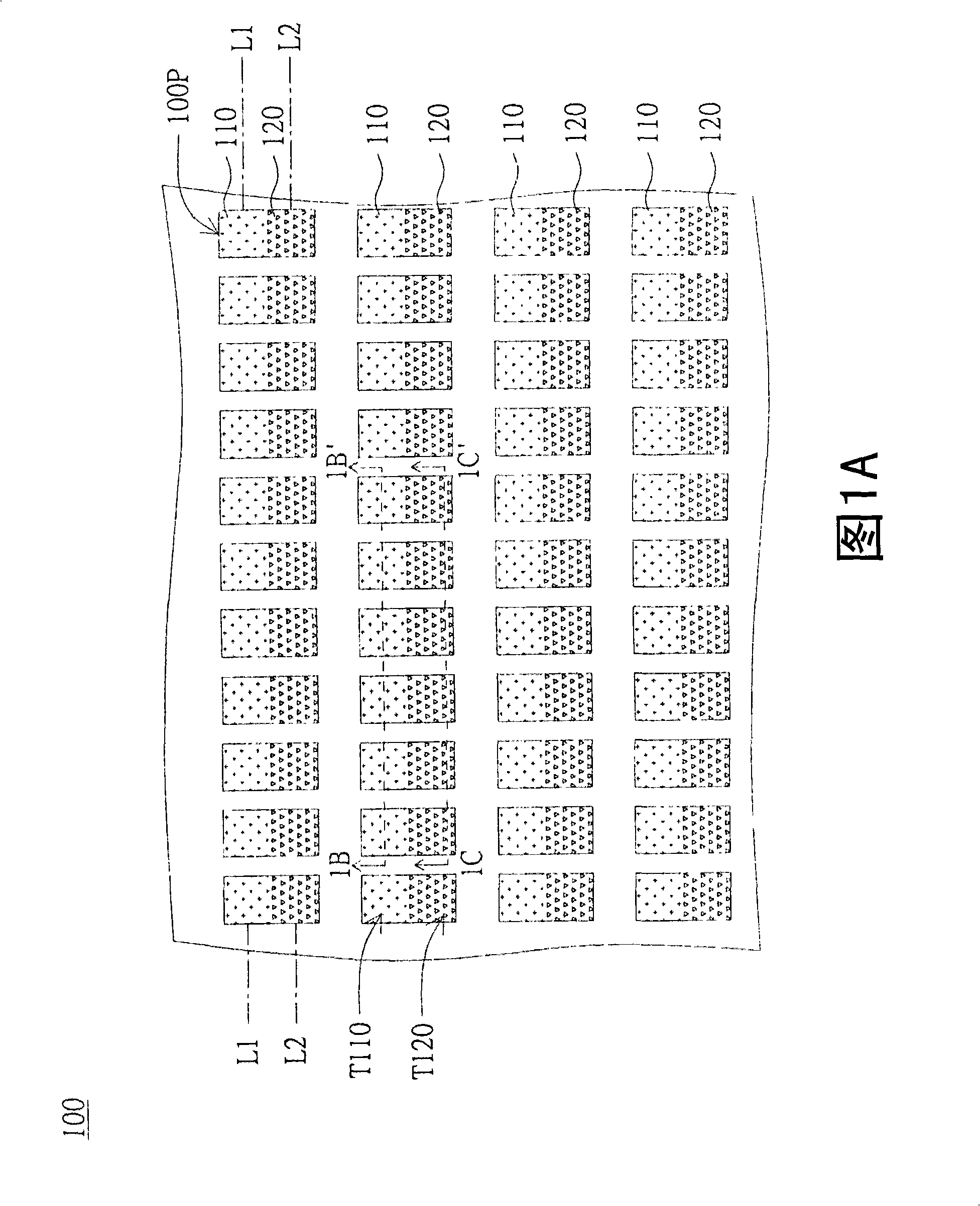
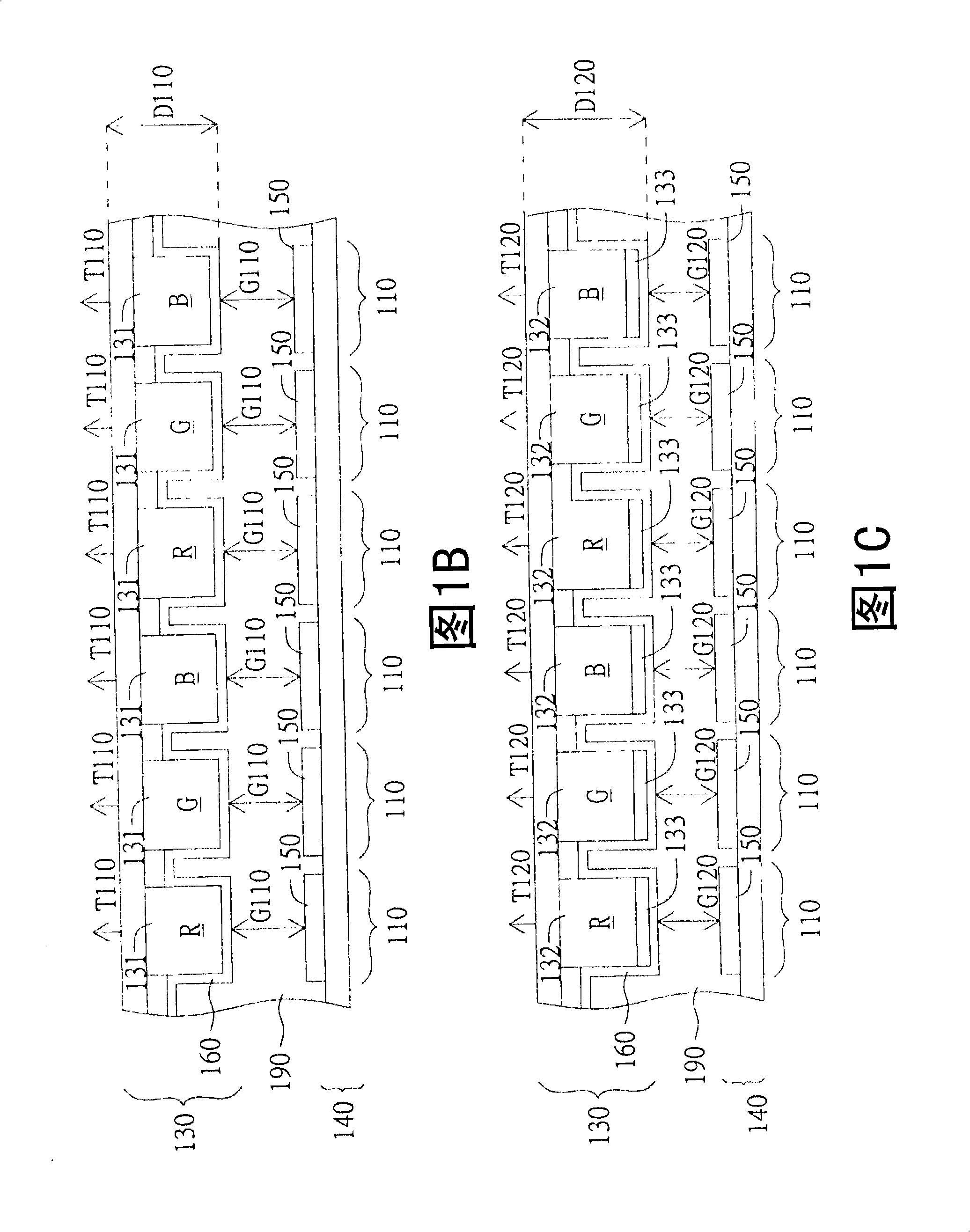
[0028] Please refer to FIG. 1A , which shows a schematic diagram of a liquid crystal display panel 100 according to a first embodiment of the present invention. The liquid crystal display panel 100 is applied to a liquid crystal display device, such as a desktop computer screen, a liquid crystal television, a mobile phone screen, a personal digital assistant (PDA) screen, or various electronic devices using the liquid crystal display panel as a display interface. The liquid crystal display panel 100 includes a plurality of sub-pixels (sub-pixels) 100P. The sub-pixel 100P is the smallest display unit of the liquid crystal display panel 100 and is used to display primary colors, such as red (Red), green (Green) and blue (Blue). Each sub-pixel 100P has a first display area 110 and a second display area 120 . Each first display area 110 has a first transparency T110, and each second display area 120 has a second transparency T120. In FIG. 1A , the first display area 110 / the se...
no. 2 example
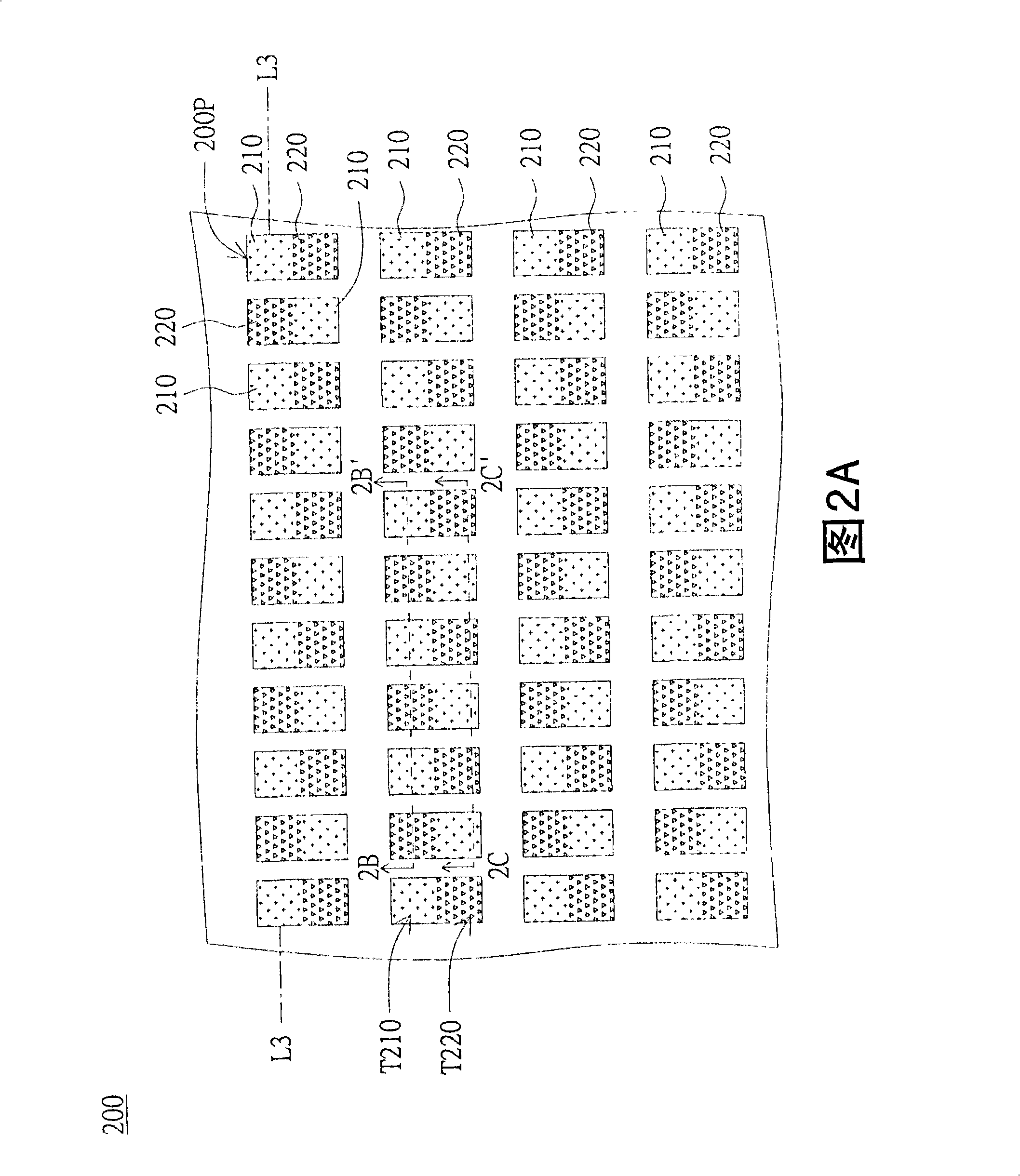
[0045] The difference between the liquid crystal display panel 200 of this embodiment and the liquid crystal display panel 100 of the first embodiment lies in the arrangement positions of the first display area 210 and the second display area 220 , and the rest of the similarities will not be repeated here. Please refer to FIG. 2A , which shows a schematic diagram of a display panel 200 according to a second embodiment of the present invention. In this embodiment, the first display area 210 and the second display area 220 are alternately arranged on the straight line L3. In FIG. 2A , the first display area 210 / the second display area 220 and their first transparency T210 / second transparency T220 are distinguished by different dots. It means that each first display area 210 is not adjacent, and each second display area 220 is not adjacent.
[0046] Please refer to FIG. 2B and FIG. 2C at the same time. FIG. 2B shows a cross-sectional view of the liquid crystal display panel...
no. 3 example
[0051] The difference between the liquid crystal display panel 300 of this embodiment and the liquid crystal display panel 100 of the first embodiment lies in how the first display area 310 and the second display area 320 are formed, and the rest of the similarities will not be repeated here. Please refer to FIG. 3A , which shows a schematic diagram of a liquid crystal display panel 300 according to a third embodiment of the present invention. Each sub-pixel 300P has a first display area 310 and a second display area 320 . Each first display area 310 has a first transparency T310, and each second display area 320 has a second transparency T320. Wherein, the first penetration T310 and the second penetration T320 are not substantially equal. In FIG. 3A , the first display area 310 / the second display area 320 and their first transparency T310 / second transparency T320 are distinguished by different dots.
[0052] Please refer to FIG. 3B and FIG. 3C at the same time. FIG. 3B ...
PUM
 Abstract
Description
Claims
Application Information
 - R&D
- Intellectual Property
- Life Sciences
- Materials
- Tech Scout
- Unparalleled Data Quality
- Higher Quality Content
- 60% Fewer Hallucinations
Browse by: Latest US Patents, China's latest patents, Technical Efficacy Thesaurus, Application Domain, Technology Topic, Popular Technical Reports.
© 2025 PatSnap. All rights reserved.Legal|Privacy policy|Modern Slavery Act Transparency Statement|Sitemap|About US| Contact US: help@patsnap.com