
Projection lens device and projection display apparatus using the same

A projection lens and lens technology, applied in the field of projection lens, can solve the problem of increasing manufacturing cost, and achieve the effects of ensuring back intercept, high projection performance, and reducing manufacturing cost

Active Publication Date: 2008-11-26
FUJIFILM CORP
View PDF2 Cites 7 Cited by
  • Summary
  • Abstract
  • Description
  • Claims
  • Application Information

AI Technical Summary

Problems solved by technology

[0013] However, in the projection lenses of the aforementioned Patent Documents 3 and 4, there is no concept of inserting a light reflection element into the optical path.
Moreover, in the projection lenses of the above-mentioned Patent Documents 1 and 2, as the light reflection element inserted in the optical path, in order to make up for the narrow space, instead of using a light reflection mirror, a prism that can increase the optical path length is used, so the manufacturing cost becomes lower. high problem

Method used


Image

  • Projection lens device and projection display apparatus using the same
  • Projection lens device and projection display apparatus using the same
  • Projection lens device and projection display apparatus using the same

Examples


Embodiment 1

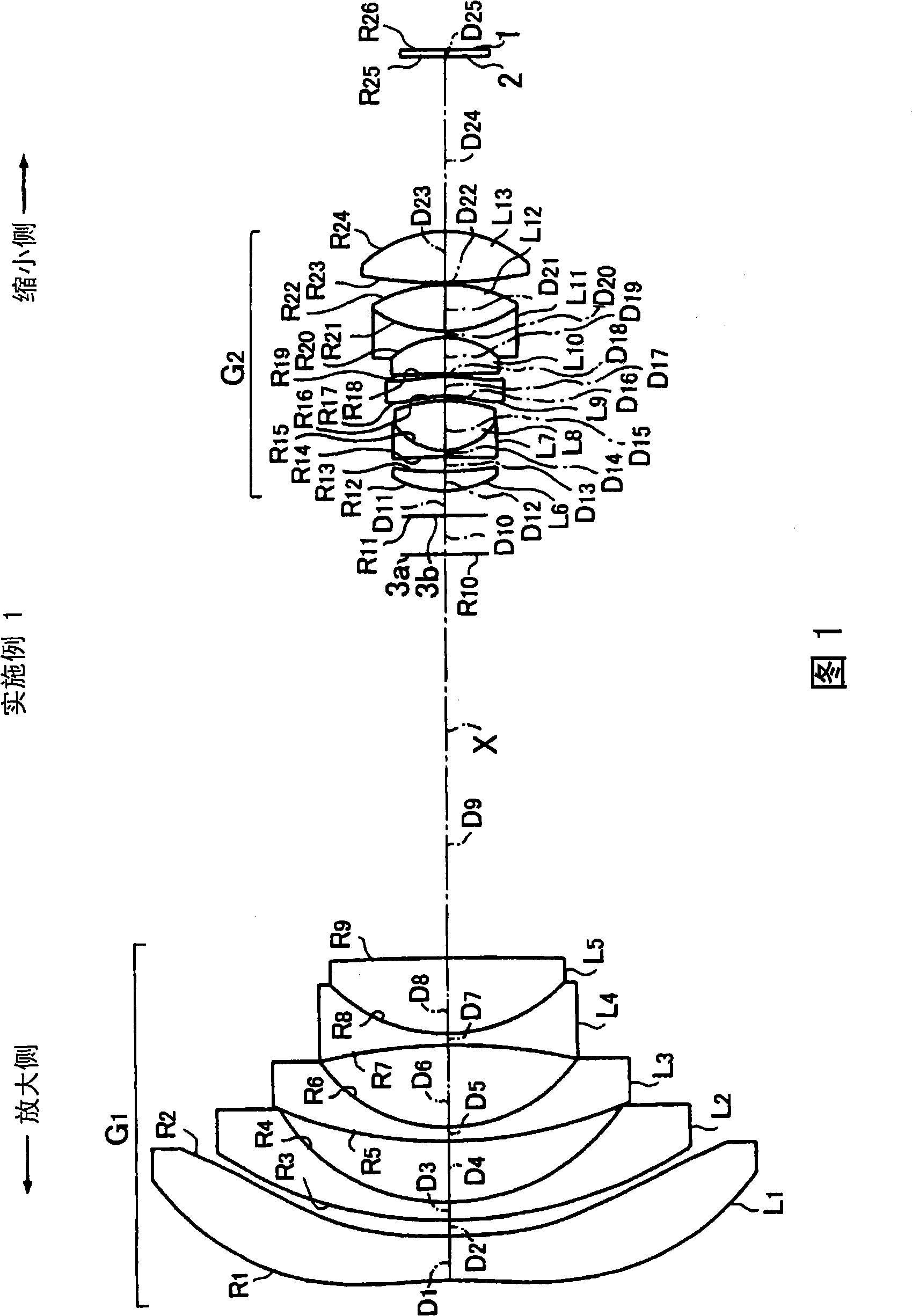
[0129] As shown in FIG. 1 , in the projection lens according to Example 1, the first lens group G having negative refractive power is arranged in order from the magnification side. 1 , mask 3a and aperture stop 3b, and the second lens group G with positive refractive power 2 In this configuration, the reduction side is set to be substantially telecentric. It should be noted that Fig. 2 shows the first lens group G of the projection lens in Fig. 1 1 and the second lens group G 2 A configuration in which an optical reflection mirror 4 as an optical path deflecting means for deflecting the optical path is disposed therebetween.

[0130] 1st lens group G 1 Arranged in order from the magnification side: the first lens L consisting of an aspheric lens with a small refractive power 1 , The second lens L consisting of a negative meniscus lens with a concave surface facing the reduction side 2 and third lens L 3 , and the fourth lens L consisting of two concave lenses 4 and the ...

Embodiment 2

[0189] The configuration of the projection lens according to Example 2 is as shown in FIG. 3 , and the first lens group G having negative refractive power is arranged in order from the magnification side. 1 , aperture stop (mask) 3a, 3b, and the second lens group G with positive refractive power 2 The point that the reduction side is substantially telecentric is the same as that of the projection lens according to the first embodiment.

[0190] 1st lens group G 1 The first lens L consisting of an aspheric lens with a small refractive power is arranged in order from the magnification side 1 , The second lens L consisting of a negative meniscus lens whose concave surface faces the reduction side 2 and third lens L 3 , the fourth lens L consisting of two concave lenses 4 , according to the fifth lens L composed of a negative lens 5 and 7th lens L 7 Sixth lens L sandwiching two convex lenses 6 3-piece cemented lens, and the 8th lens L consisting of two convex lenses 8 .

...


PUM


Abstract

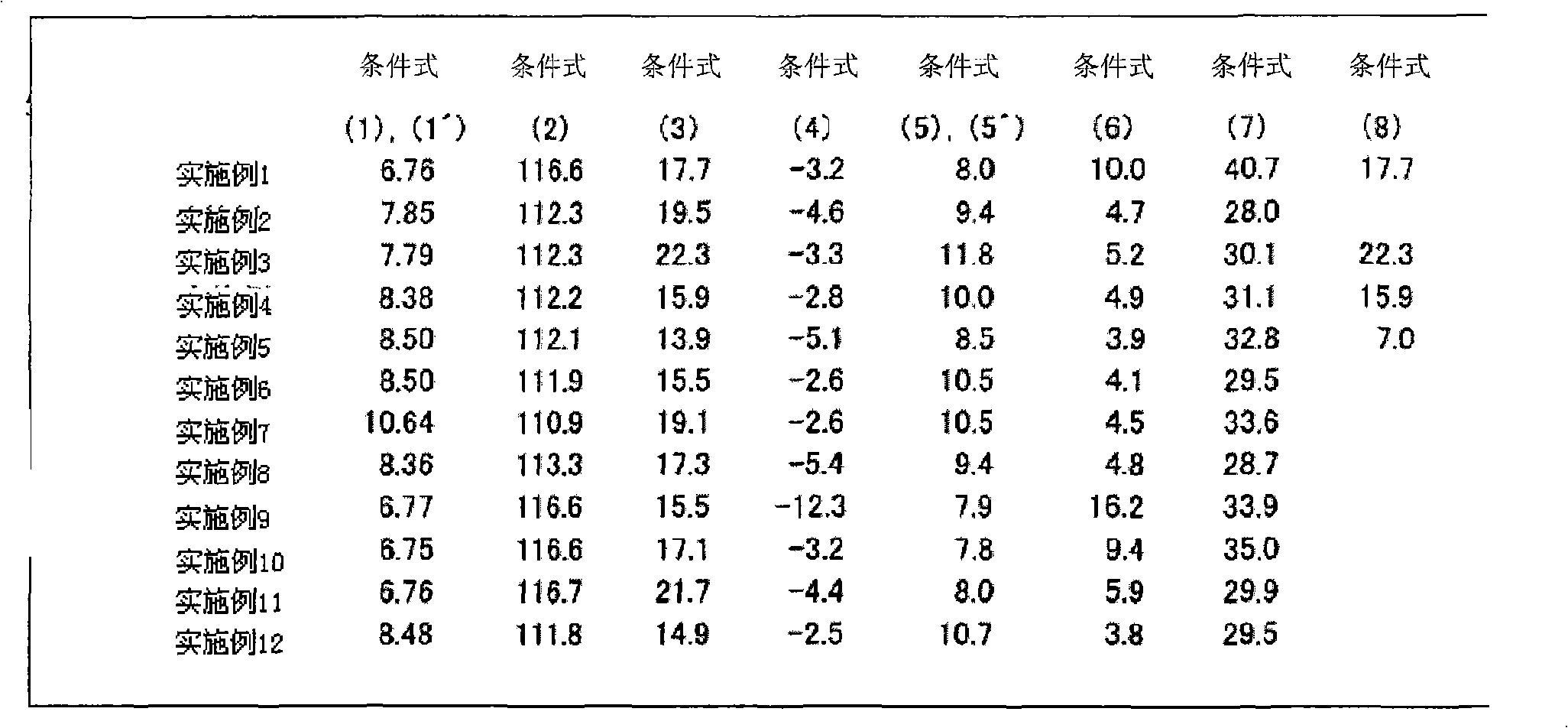
A projection lens device includes, in order from a magnification side, a first lens group G1 having a negative refractive power, and a second lens group G2 having a positive refractive power. The projection lens device is substantially telecentric on a reduction side thereof. The second lens group G2 includes a three-element cemented lens L10 to L12 formed by cementing three lens elements. A space between the first lens group G1 and the second lens group G2 is set as the maximum inter-lens space (the maximum air space) so that a reflection mirror 4 can be inserted. Also, the projection lens device satisfies eight conditional expressions.

Description

technical field [0001] The present invention relates to a projection lens for magnifying and projecting display information from a light valve such as a transmissive or reflective liquid crystal display element or a DMD (digital micro-mirror device), and particularly relates to a projection lens suitable for rear projection A projection lens for a display device and a projection display device using the projection lens. Background technique [0002] Conventionally, the following devices are known as projection-type display devices: a front-mounted device in which a projection lens is arranged on the same side as the viewer with respect to the screen, and the light emitted by the projection lens is imaged on a reflective screen; The rear-mounted device is configured in such a way that the audience clamps the screen and makes the light emitted by the projection lens image on the transmissive screen. [0003] Among them, among the rear projection type display devices, there is...

Claims


Application Information

Patent Timeline
Patent Type & Authority Applications(China)
IPC IPC(8): G02B13/16G02B13/18G03B21/00
CPCG02B13/04G03B21/28G02B13/16G03B33/12G02B13/22G03B21/10
Inventor 山本力
Owner FUJIFILM CORP
Learn More