
Knife with retractable blade, usable particularly in a hostile environment

A blade and operating system technology, applied in metal processing and other directions, can solve problems such as complex processes, increase the risk of blade accidents, and achieve the effect of stable grip

Inactive Publication Date: 2008-11-26
阿海珐核循环公司
View PDF0 Cites 7 Cited by
  • Summary
  • Abstract
  • Description
  • Claims
  • Application Information

AI Technical Summary

Problems solved by technology

and having to grip these knives differently depending on whether someone is moving the blade or adjusting it can lead to an overly complicated process
Finally, these clumsy movements likely increase the risk of accidents when the blades are opened

Method used


Image

  • Knife with retractable blade, usable particularly in a hostile environment
  • Knife with retractable blade, usable particularly in a hostile environment
  • Knife with retractable blade, usable particularly in a hostile environment

Examples


Embodiment Construction

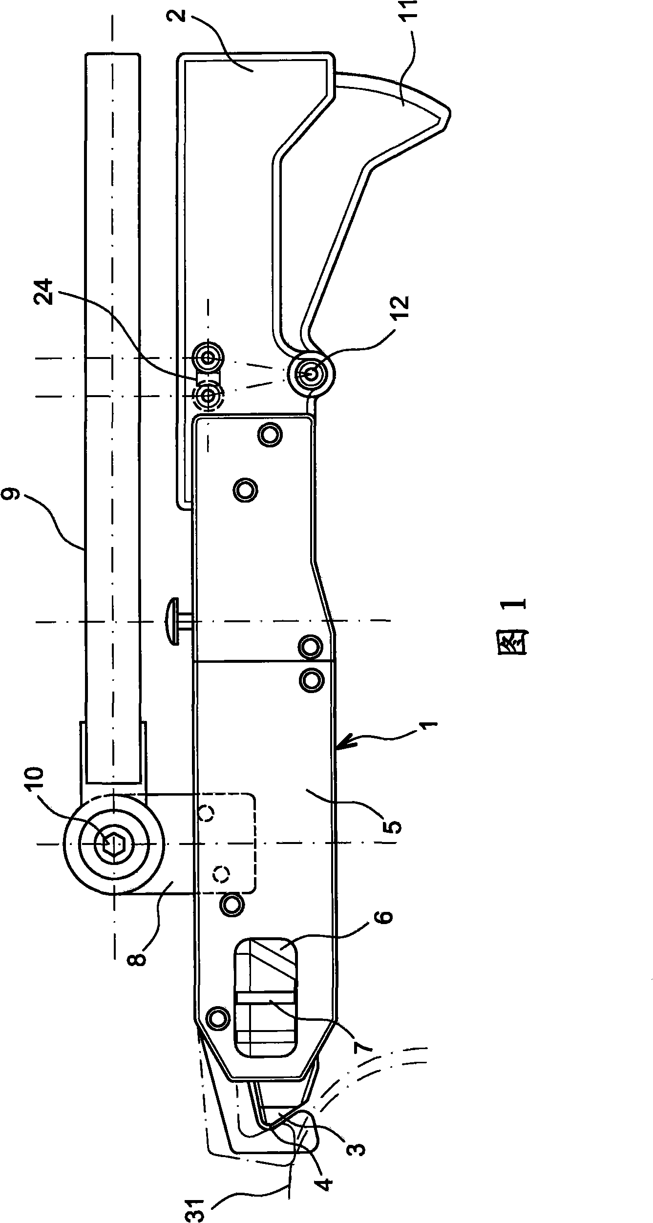
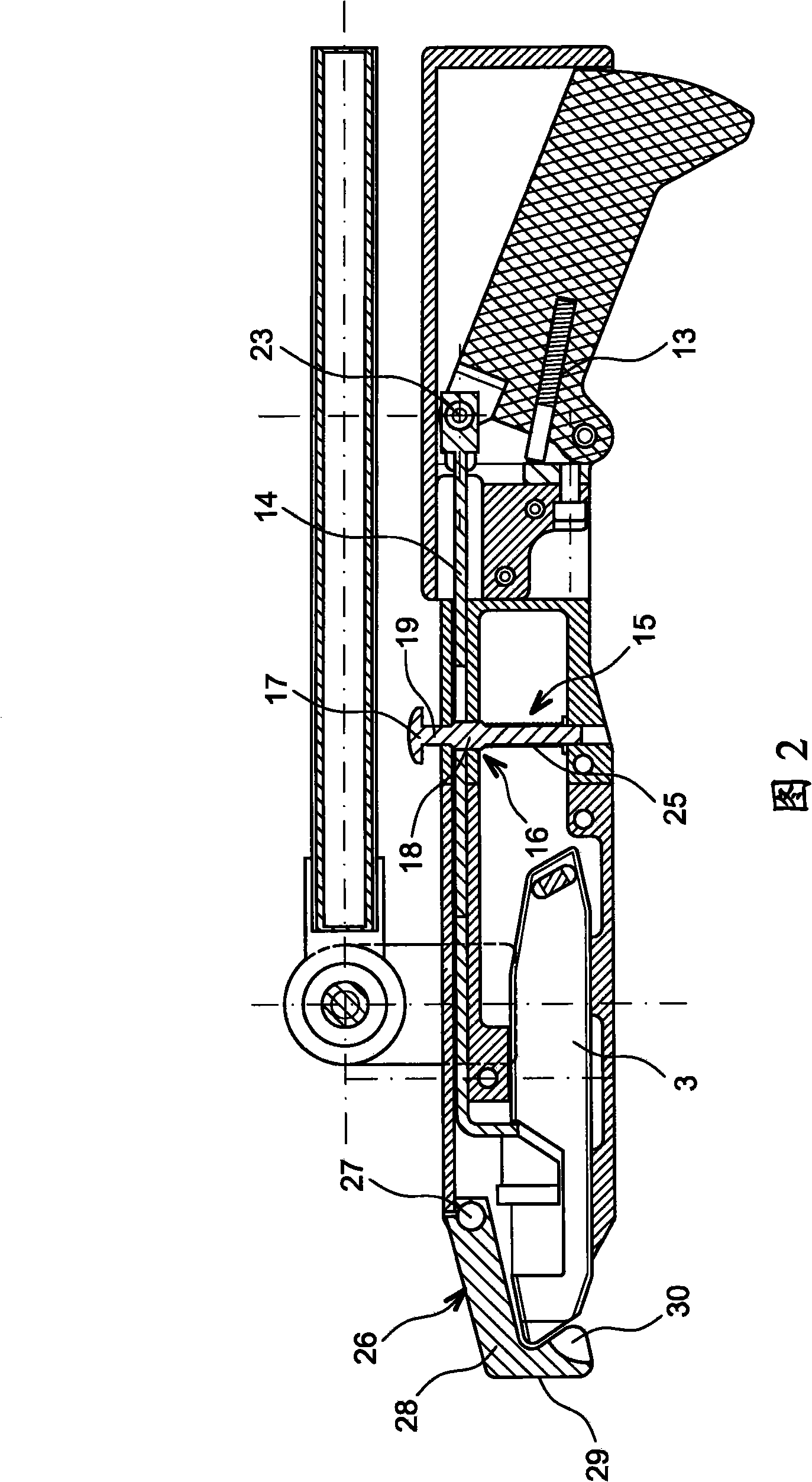
[0008] The description provided above mainly refers to FIGS. 1 and 2 . The body of the knife includes a sheath 1 at the front and a handle 2 at the rear, and the sheath and the handle are connected together by screws. A common type of blade 3 with a beveled leading edge including a tip 4 is located in a sheath 1 in which it slides. The sheath 1 includes a removable capotage 5 which is used to create an opening in the sheath to provide access to the blade 3 and to replace the blade. In order to make a part of the blade 3 visible in all cases, a window-like opening 6 is formed through the cover 5 to check the position of the blade by means of the position of the guide marks 7 or other orientation marks.

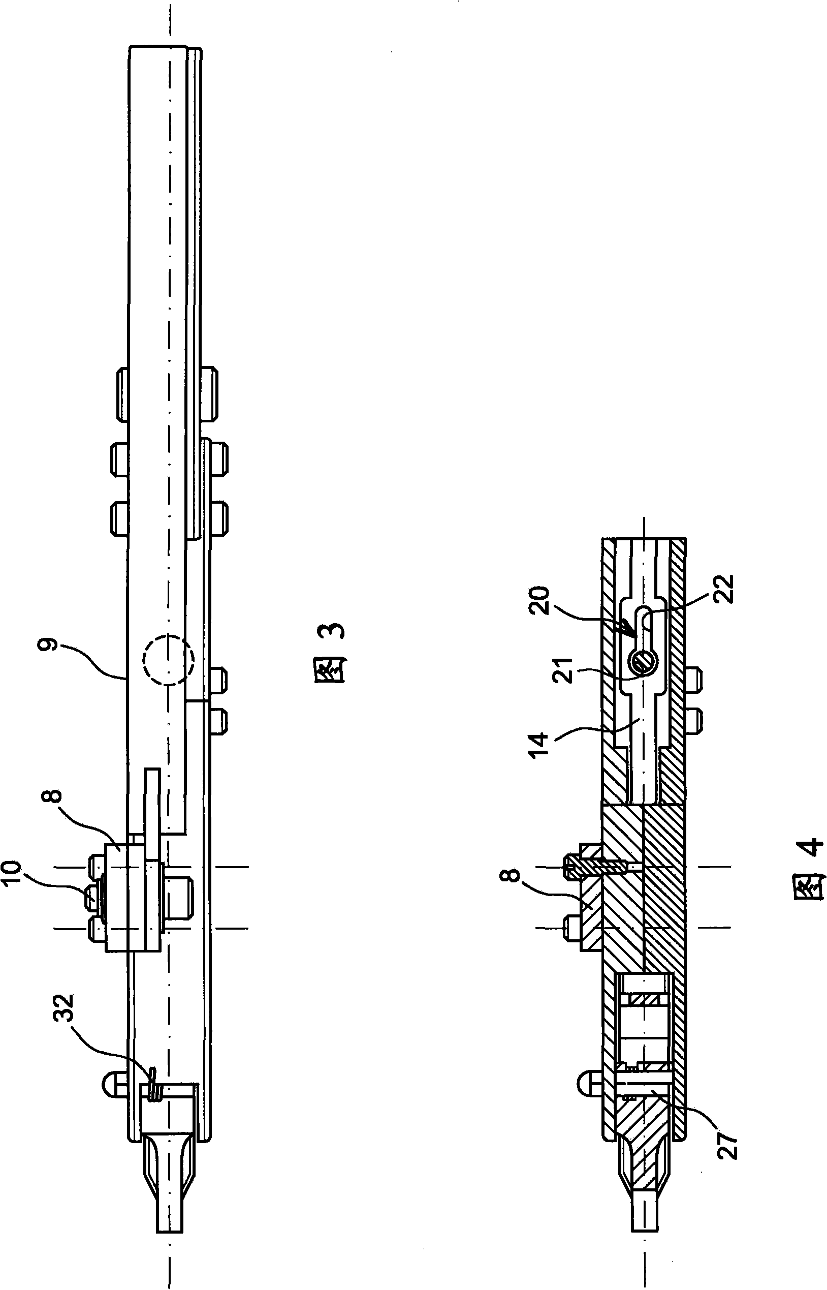
[0009] A patte 8 is fixed to the sheath 1, on which a gripping bar 9 is hinged by means of an axis 10, the direction of which is transverse. The bracket 8 and the rod 9 are located above the sheath 1 and the handle 2 . The rod 9 is hinged to the shaft 10 so that it turns fro...


PUM


Abstract

The knife comprises a sheath (1), a handle (2) at the rear, a sliding blade, an actuating system comprising a trigger (11) underneath the handle, a transmission rod, and a hand grip bar (9). The tool is grasped in both hands, with sufficient dexterity even in difficult conditions. Application to work in a hostile environment.

Description

technical field [0001] The subject of the invention is a knife with a telescopic blade ("telescopic cutting knife") adapted to work in special situations, such as working in harsh environments, where a direct grasp of the tool is not possible. Background technique [0002] Working in harsh environments is accomplished with a glove box, where the operator inserts his (or her) arms into a wall with a master and slave arm that mimics the operator's motion on the other side of the protective wall. remote control machine. The operator cannot achieve complete freedom of movement and does not feel the same sensations as he would feel under normal working conditions, thus reducing dexterity. As a result, many tasks become difficult to perform, wherein, in the application considered here with regard to telescoping knives, the actions of opening and retracting the blade, and locking the blade at a selected position are usually accomplished by manipulating a small mechanism on the kni...

Claims


Application Information

Patent Timeline
IPC IPC(8): B26B5/00B26B29/02
CPCB26B1/08B26B29/02B26B5/001
Inventor 文森特·莱格尔让-马克·瓦德乌克斯
Owner 阿海珐核循环公司
Learn More