Vibrocompacting device

A technology of molding machine and vibrating table, which is applied in the direction of presses, material forming presses, manufacturing tools, etc., and can solve problems such as difficult to determine and narrow working range

Inactive Publication Date: 2008-11-26
SOLIOS CARBONE
View PDF0 Cites 1 Cited by
  • Summary
  • Abstract
  • Description
  • Claims
  • Application Information

AI Technical Summary

Problems solved by technology

These jobs may appear to be very narrow and often difficult to define

Method used


Image

  • Vibrocompacting device

Examples


Embodiment Construction

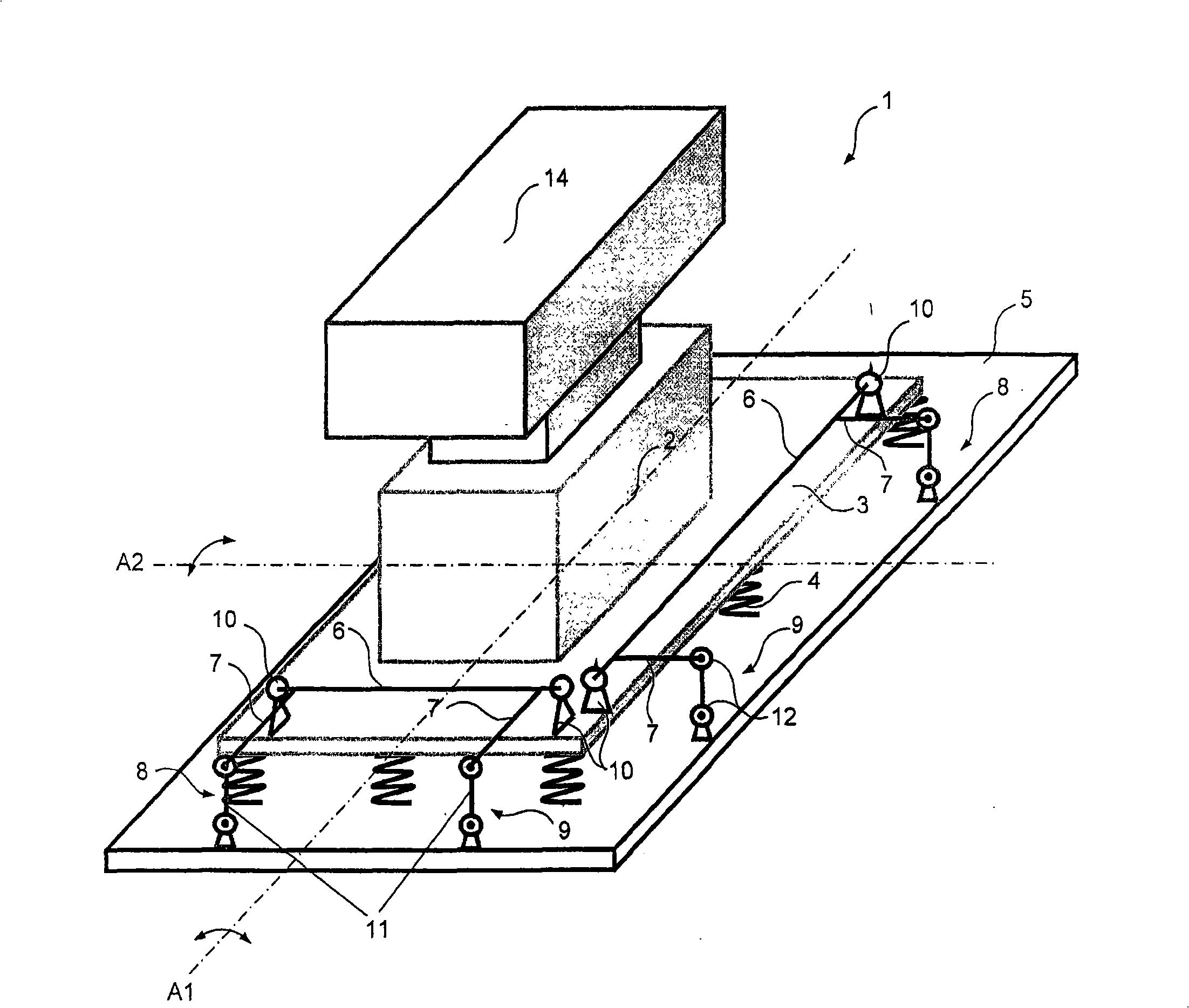
[0016] The present invention relates to a vibratory forming machine, in particular for forming molded anode blocks.

[0017] The press comprises at least one mold 2 supported directly or indirectly by a vibrating table 3 . The mold can be configured to be integrated with the vibrating table, or it can be configured to be moved and simply placed on the vibrating table.

[0018] The vibrating table 3 is fixed to the base frame 5 through the suspension device 4, and is configured to move in a vertical direction under the action of a vibration excitation device.

[0019] The term "pedestal" should be understood broadly, which may be a load-bearing structure made of metal or concrete, or the ground.

[0020] The suspension means are elastic buffer means, especially in the form of pneumatic means, such as inflatable cushions, or they may simply consist of helical springs.

[0021] The vibration excitation device may consist of a (not shown) vibration machine (unbalance device). T...


PUM


Abstract

The invention concerns a vibrocompacting device (1), in particular for forming molded anode blocks. The device comprises at least one mold (2) borne by an oscillating table (3) secured via suspension means (4) to a frame (5). The table (3) is arranged to move relatively to the frame (5) along a vertical direction under the effect of vibratory actuating means. The invention is characterized in that the device comprises stabilizing means (6, 12) for limiting, even suppressing, pitch and/or roll of the oscillating table, including at least one torsion bar (6) arranged between the oscillating table (3) and its frame (5).

Description

technical field [0001] The invention relates to an oscillating molding machine which operates in the usual manner under the action of a vibration excitation, in particular for forming molded anode blocks. Background technique [0002] Known various vibratory molding machines all comprise at least one mold supported by a vibrating table, said vibrating table is fixed to the base frame by a suspension device, and the vibrating table is arranged to move along a vertical direction under the action of a vibrating excitation device. The direction moves relative to the base frame. The base frame can be a load-bearing structure made of metal or concrete. Suspension units are often attached directly to load-bearing structures or the ground. [0003] Today, various new types of vibrating machines are mounted on suspensions in the form of resilient, inflatable air cushions to isolate vibrations and prevent them from being transmitted to the ground or the surrounding environment. [...

Claims


Application Information

Patent Timeline
Patent Type & Authority Applications(China)
IPC IPC(8): B30B11/02
CPCB30B11/022
Inventor J·-F·安德雷
Owner SOLIOS CARBONE
Why Eureka
Try Eureka