Assembly scaffold

A scaffolding and combined technology, applied in the field of scaffolding, can solve the problems of inability to assemble and disassemble by a single person, and achieve the effects of reliable locking, simple locking and unlocking operations, and expanding the scope of application.

Active Publication Date: 2008-12-03
SUZHOU PICA ALUMINUM IND
View PDF1 Cites 15 Cited by
  • Summary
  • Abstract
  • Description
  • Claims
  • Application Information

AI Technical Summary

Problems solved by technology

[0005] In order to solve the technical problem that a single person cannot assemble and disassemble in the prior art, the present invention provides a comb

Method used


Image

  • Assembly scaffold
  • Assembly scaffold
  • Assembly scaffold

Examples


Embodiment 1

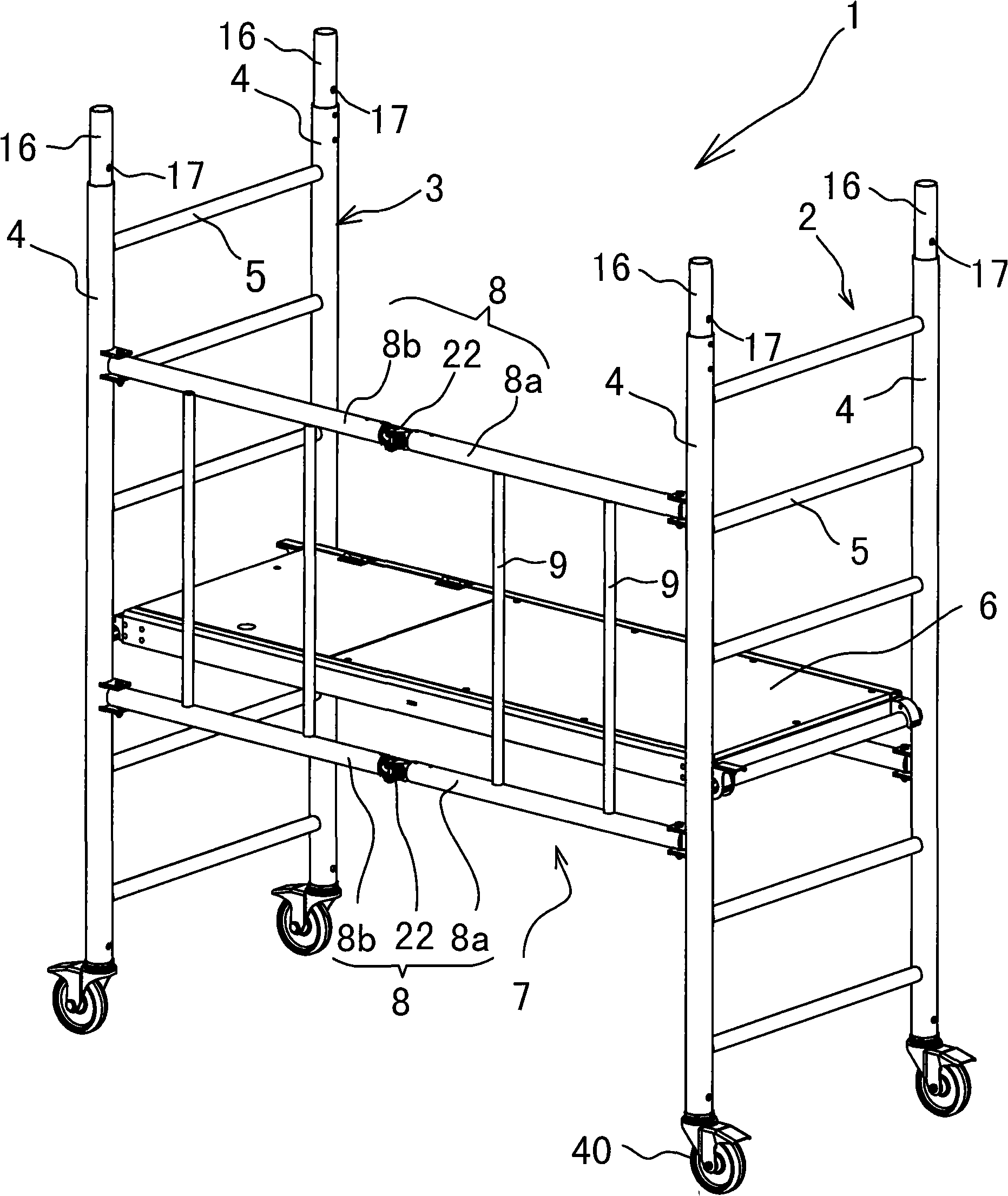
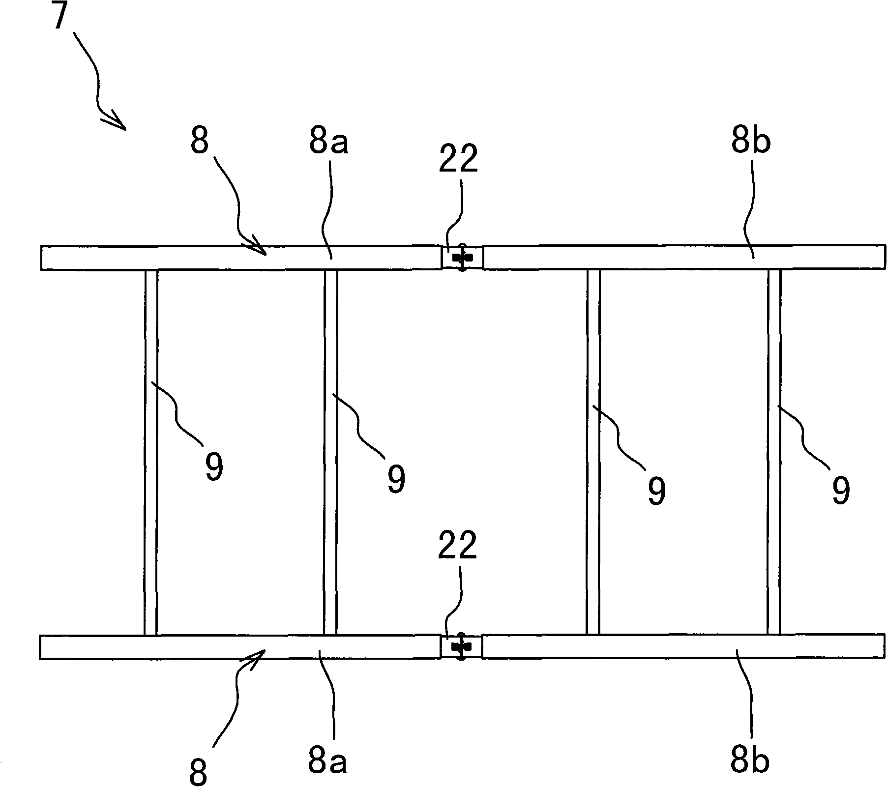
[0031] Embodiment one: see attached figure 1 ~ attached Figure 8 As shown, a combined scaffold, see attached figure 1 As shown, it consists of a bottom frame unit 1 with a working platform 6 erected. The bottom frame unit 1 has two side supports 2, 3 parallel to each other, and each side support 2, 3 is fixedly connected by a pair of columns 4 and Several parallel and evenly distributed pedal crosspieces 5 are formed between a pair of columns 4, and the two ends of the working platform 6 are respectively hooked on the opposite pedal crosspieces 5 on the two side supports 2 and 3 through two hooks. There is a folding frame 7 connected between a column 4 on the left side support 2 and the opposite same side column 4 on the right side support 3; figure 2 , the folding frame 7 is composed of two folding cross bars 8 and four longitudinal connecting rods 9 connected between the folding cross bars 8, and each folding cross bar 8 is composed of two sections of left and right cros...

Embodiment 2

[0038] Embodiment two: see attached Figure 9 ~ attached Figure 12 As shown, a combined scaffold differs from the first embodiment in that: it is based on the first embodiment to install a heightening frame unit 10, and the heightening frame unit 10 is as attached Figure 9 As shown, it is composed of two side brackets 11, 12 parallel to each other on the left and right, and a cross brace 13 and a diagonal brace 14 are overlapped. An embedding hole is provided, and an embedding end 16 is correspondingly provided on the top of the column 4 of the bottom frame unit 1. end 16, and the column embedded end 16 of the bottom frame unit 1 and the column 15 embedding hole of the heightened frame unit 1 are correspondingly provided with a through hole 17; see the attached Figure 9 As shown, there is a locking pin 18 consisting of a pin rod 19 and a semi-annular collar 20. The pin rod 19 penetrates the embedded end 16 and pins the through hole 17 on the embedded hole, and the tail en...


PUM


Abstract

The invention relates to a combined type scaffold which comprises a bottom frame unit. The bottom frame unit is provided with two side stands; each side stand is composed of a pair of upright columns and a plurality of foot-pedal ledges; and working platforms are respectively arranged on the two side stands. The combined type scaffold is characterized in that a folding border is connected between an upright column on the left side stand and the opposite upright columns on the identical side of the right side stand; the folding border is composed of at least two folding cross bars and longitudinal connecting rods connected between the folding cross bars; each folding cross bar is formed by left and right sections of cross bars articulated on a horizontal plane through an articulated mechanism; the two folding cross bars are vertically distributed; the both ends of each folding cross bar are respectively articulated with the upright columns of the side stands on the horizontal plane; a positioning mechanism is locked to form an unfolded state during the unfolding process of the folding border; and the folding frame is folded towards the inner side of the scaffold to form a folded state after the positioning mechanism is unlocked. The combined type scaffold has the advantages that the assembly and the disassembly can be completed by a single person, the combined type scaffold is especially suitable for the occasions on which construction is performed by a single person, and the application range is wider.

Description

technical field [0001] The invention relates to a scaffold for building construction, in particular to a combined scaffold. Background technique [0002] Traditional scaffolding is built by construction workers on the construction site with individual steel pipes. It requires tools to build and dismantle. It is difficult, slow, and inefficient, which affects the construction progress. It is also bulky and inconvenient to move. [0003] Therefore, a special scaffold product appeared on the market later - combined scaffolding. The combined scaffolding is mostly made of profiles and light in weight. It only needs to be overlapped with a pre-designed structure when used. The lapped assembly is simple and convenient. improve. The more advanced structure in the existing combined scaffolding can be seen in the invention patent of ZL200420094998.8 in the patent No. announced on February 8, 2006 in the Chinese Patent Announcement. A combined scaffold is disclosed in this patent tec...

Claims


Application Information

Patent Timeline
IPC IPC(8): E04G1/14E04G1/15
Inventor 范刚
Owner SUZHOU PICA ALUMINUM IND
Why Eureka
Try Eureka