Ultrasonic wave pressure transducer and air pressure monitoring device

A pressure sensor and air pressure monitoring technology, applied in the direction of fluid pressure measurement using acoustic methods, can solve the problem that the frequency cannot be lower than 0.1Hz, and achieve the effect of simple identification and easy identification

Inactive Publication Date: 2008-12-03
拉尔夫·克林伯格
View PDF0 Cites 7 Cited by
  • Summary
  • Abstract
  • Description
  • Claims
  • Application Information

AI Technical Summary

Problems solved by technology

Using various existing sound pressure microphones as pressure sensors, the air pressure change of 0.1Pa can be measured, but its frequenc

Method used


Image

  • Ultrasonic wave pressure transducer and air pressure monitoring device
  • Ultrasonic wave pressure transducer and air pressure monitoring device
  • Ultrasonic wave pressure transducer and air pressure monitoring device

Examples


Embodiment Construction

[0035] The present invention will be further described below in conjunction with the drawings and embodiments:

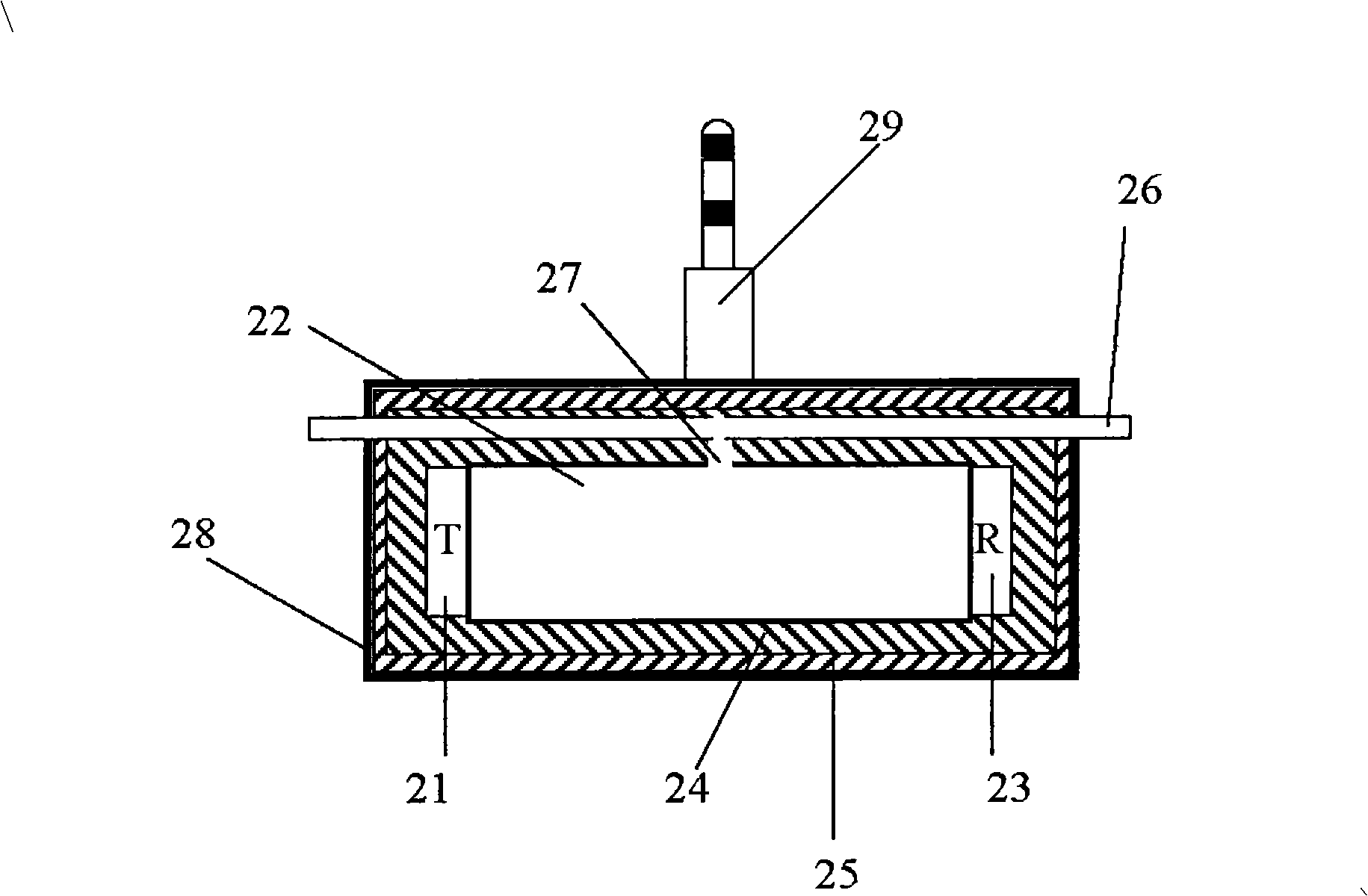
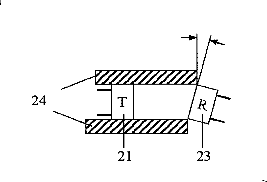
[0036] figure 2 It is a schematic diagram of the structure of the first embodiment of the ultrasonic pressure sensor of the present invention. Such as figure 2 As shown, the ultrasonic pressure sensor is mainly composed of a tube body 22, an ultrasonic transmitter 21 provided at one end of the tube body 22, and an ultrasonic receiver 23 provided at the other end of the tube body 22. The tube body 22 may be made of plastic, metal or sponge-like material, and an opening 27 for introducing external air into the tube body is opened on the tube body 22 to ensure that the air pressure in the tube body 22 is equal to the monitored external ambient air pressure. The ultrasonic waves generated from the ultrasonic transmitter 21 propagate through the air in the tube and are received by the ultrasonic receiver 23. The propagation of ultrasonic waves from the transmitting end to...


PUM


Abstract

The invention relates to an ultrasonic pressure sensor and an atmospheric pressure monitoring device using the ultrasonic pressure sensor. The ultrasonic pressure sensor comprises a pipe body provided with an air inlet, an ultrasonic transmitter arranged at one end of the pipe body and used for transmitting ultrasonic waves, an ultrasonic receiver arranged at the other end of the pipe body, and an outer shell which contains the pipe body, the ultrasonic transmitter and the ultrasonic receiver. The ultrasonic receiver receives an ultrasonic wave transmitted through air in the pipe body, and according to the received ultrasonic wave, outputs sinusoidal voltage, the amplitude of which is in proportion with the atmospheric pressure in the pipe body. The atmospheric pressure monitoring device can effectively detect barometric fluctuation with the amplitude ranging from 0.1Pa to 50Pa and the frequency ranging from 0.02Hz to 2Hz, and display in various direct-viewing manners the barometric fluctuation with negative impacts on the human body.

Description

Technical field [0001] The invention relates to air pressure detection, and more specifically, to an ultrasonic pressure sensor and an air pressure monitoring device using the ultrasonic pressure sensor. Background technique [0002] The atmospheric pressure is constantly changing all the time, as shown in Figure 1 is a graph of the atmospheric pressure change on a certain day. In the two-minute period shown at A and B, there may be two types of changes in atmospheric pressure, one is a completely constant or smooth change (A1 and B1), and the other is a fluctuation (A2 and B2). These air pressure fluctuations are usually in the range of 0.1 Pa to 50 Pa, and the frequency is 0.02 Hz to 2 Hz. The waveform of these fluctuations may be irregular, or it may be similar to a sine wave. [0003] Absolute air pressure will have an impact on changes in the weather, but will not have a direct negative impact on the human body. The human body can adjust itself to adapt to different absolute...

Claims


Application Information

Patent Timeline
IPC IPC(8): G01L11/06
Inventor 拉尔夫·克林伯格
Owner 拉尔夫·克林伯格
Why Eureka
Try Eureka