
Test method for accurately simulating bond-slip property of male pin in tensile area

A bond-slip, test method technology, applied in the testing of machine/structural components, the use of a stable shear force to test the strength of materials, measuring devices, etc., can solve problems such as the inaccurate simulation of bond-slip properties, To achieve the effect of convenient operation

Inactive Publication Date: 2008-12-03
XUZHOU UNIV OF TECH
View PDF0 Cites 14 Cited by
  • Summary
  • Abstract
  • Description
  • Claims
  • Application Information

AI Technical Summary

Problems solved by technology

[0011] (3) The yield strength of the connector material must be tested;
For studs in tension regions, the bond-slip behavior cannot be accurately simulated by push-out tests

Method used


Image

  • Test method for accurately simulating bond-slip property of male pin in tensile area
  • Test method for accurately simulating bond-slip property of male pin in tensile area
  • Test method for accurately simulating bond-slip property of male pin in tensile area

Examples


Embodiment Construction

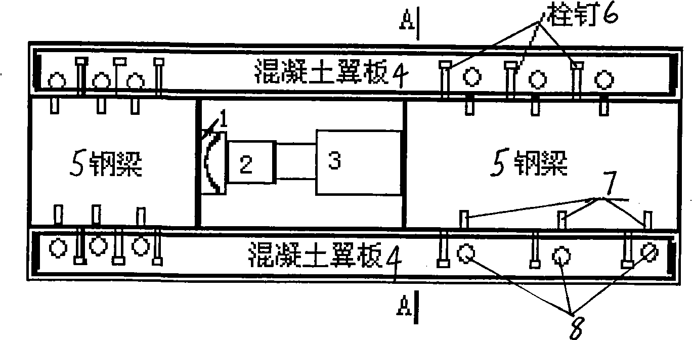
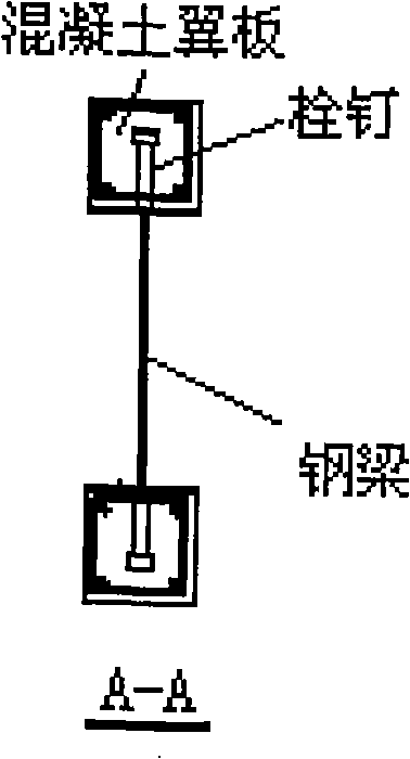
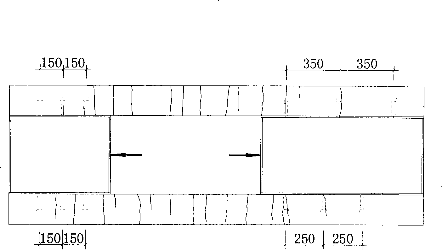
[0028] According to the current "Code for Design of Steel Structures" and Eurocodes, two sets of push-out tests are used to combine, and the steel beams and concrete wings are placed horizontally, such as figure 1 with figure 2 Shown: the establishment of a self-balanced test system built by combining two tensile specimens:

[0029] The first step is to combine the two push-out test pieces specified in the specification, and place the two steel beams 5 welded with studs 6 and the concrete wing plate template horizontally; in this embodiment, the upper and lower sides of each steel beam The three studs are evenly distributed. In order to facilitate the installation of the displacement sensor, a sensor baffle 8 is provided corresponding to each stud along the shear plane for installing the displacement sensor 7;

[0030] The second step is to pour the concrete. At this time, pay attention to the verticality of the embedded baffle plate and the wing plate; make the stud 6 and the s...


PUM


Abstract

The invention discloses a test method which can accurately simulate the bond-slip properties of a stud connector in a tensile area in a combined structure. The method comprises the steps of combining two push-out samples; reserving a space for a jack between the two samples; loading through a spherical hinge; conveniently arranging a displacement sensor on a shearing surface; measuring relative slippage between a steel beam and a concrete slab, thus accurately simulating the constructive relations and the bearing capacity of the bond-slip properties of the stud connector in the tensile area of a combination beam. The method can accurately simulate the mechanical properties of the stud in the tensile area of a beam-type component in a combined structure of steel beam and concrete. Furthermore, the method is convenient to operate.

Description

Technical field [0001] The invention relates to the field of structural engineering, in particular to a test method for accurately simulating the bonding and sliding performance of studs in a tension zone. It is especially suitable for the test of studs in the tension zone of beam members in steel-concrete composite structures. Background technique [0002] Composite structures (Composite Structures) refer to steel-concrete composite members or structures that are connected to each other by bonding, mechanical engagement or connecting pieces of steel and concrete, and can share functions. As a structural form of extremely innovative space, it has been further developed in the new century. [0003] Steel-concrete composite structure is a composite structure formed by combining steel beams and concrete slabs through shear connectors. Shear connectors can make steel beams and concrete slabs work together. Shear connectors are a key component to ensure the combined effect. Due to the...

Claims


Application Information

Patent Timeline
Patent Type & Authority Applications(China)
IPC IPC(8): G01N3/24G01N19/04G01M19/00G01M99/00
Inventor 殷惠光王景全陈柏林姜慧李国富李雁朱炯雷金果
Owner XUZHOU UNIV OF TECH
Learn More