
Method for controlling torsion oscillator with preset frequency and generating steady vibration amplitude

A control method and technology of predetermined frequency, applied in the directions of instruments, installation, optics, etc., can solve the problems of narrowing scanning angle and application limitations, saving time for calculating resonance frequency, simplifying control methods, and reducing manufacturing costs.

Inactive Publication Date: 2010-09-29
OPUS MICROSYSTEMS CORP
View PDF5 Cites 0 Cited by
  • Summary
  • Abstract
  • Description
  • Claims
  • Application Information

AI Technical Summary

Problems solved by technology

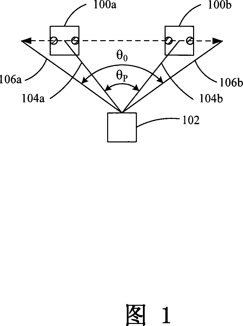
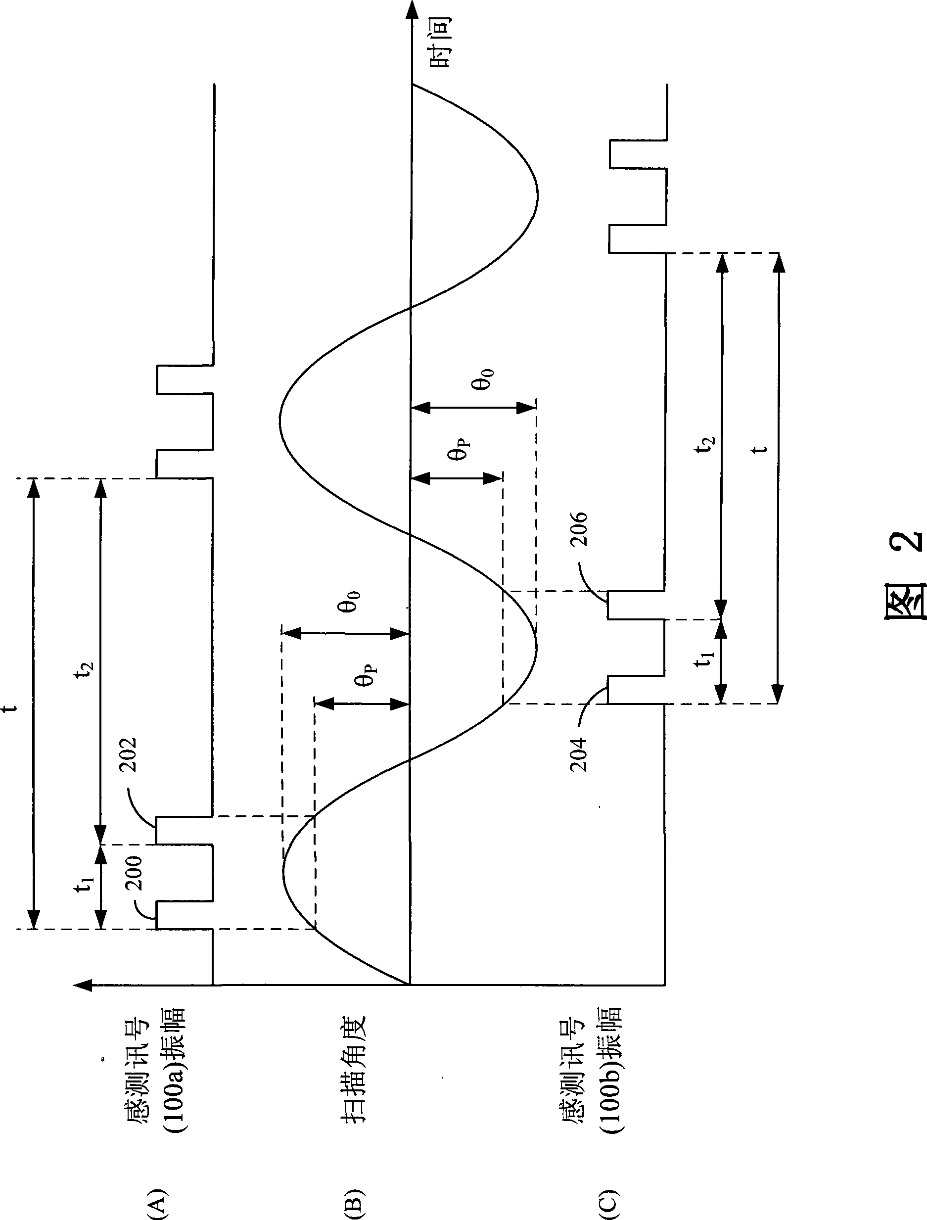
Due to the scanning angle θ formed by the laser beam (104a, 104b) at the left sensor 100a and the right sensor 100b P The scan angle θ formed by the left scan limit 106a and the right scan limit 106b of the laser beam (104a, 104b) is smaller than 0 , so the scan angle available for the torsional oscillator 102 is reduced and its application is limited

Method used


Image

  • Method for controlling torsion oscillator with preset frequency and generating steady vibration amplitude
  • Method for controlling torsion oscillator with preset frequency and generating steady vibration amplitude
  • Method for controlling torsion oscillator with preset frequency and generating steady vibration amplitude

Examples


Embodiment Construction

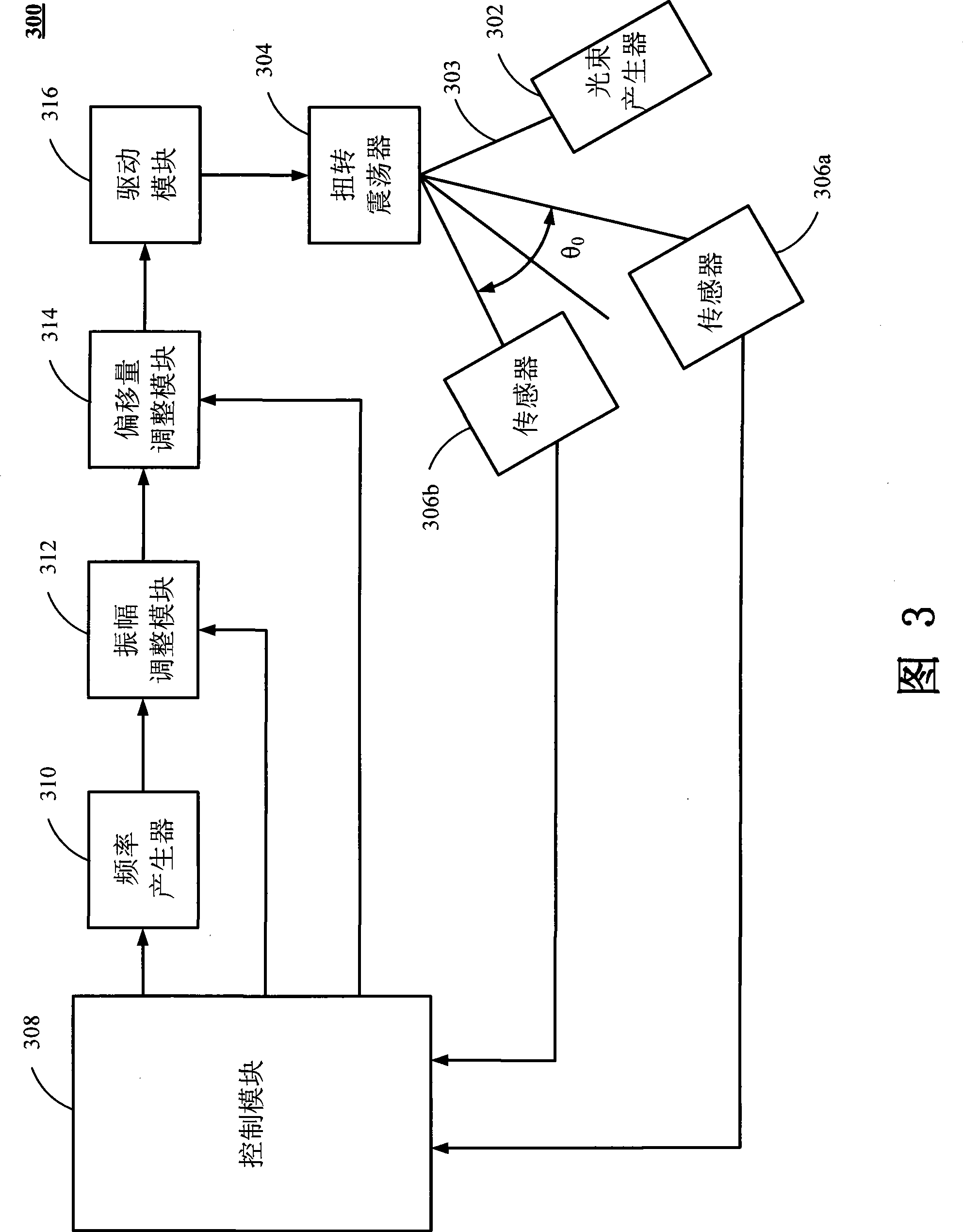
[0038] Please refer to image 3 , which is a schematic diagram of a control system of a torsional oscillator according to an embodiment of the present invention. The control system 300 is suitable for imaging devices, such as laser printers, copiers, fax machines, barcode scanners, laser projectors, laser radar and laser scanning sensors, etc. The control system 300 mainly includes a beam generator 302, a torsional oscillator 304, a sensor 306 , a control module 308 , a frequency generator 310 , an amplitude adjustment module 312 , an offset adjustment module 314 , and a drive module 316 . The beam generator 302 is, for example, a laser generator for generating the beam 303 . The torsional oscillator 304 is provided with a mirror (not shown), when a driving energy drives the mirror, the mirror rotates and reflects the light beam 303 to form a scanning angle θ 0 . The sensor 306 receives the reflected light beam from the torsional oscillator 304 and forms a sensing signal ac...


PUM


Abstract

The invention relates to a method for controlling a torsional oscillator to generate stable oscillation amplitude at the predetermined frequency. The method comprises the following steps: a control module generates a predetermined frequency and a driving energy accurate position, and the frequency of the driving energy accurate position is related to the predetermined frequency. The driving energy accurate position is utilized to drive the torsional oscillator, so that the torsional oscillator is rotated to generate a scanning angle; then the difference between the scanning angle corresponding to the driving energy accurate position and a standard scanning angle is compared through the control module, so as to adjust the driving energy accurate position, and to ensure the scanning angle of the torsional oscillator to be identical with the standard scanning angle.

Description

technical field [0001] The present invention relates to a control method of a torsional oscillator, in particular to a method for controlling a torsional oscillator to generate stable amplitude at a predetermined frequency. Background technique [0002] Torsion oscillator (torsion oscillator) is mainly used in laser printers, copiers, fax machines, barcode scanners, laser scanning projectors, laser radar and laser scanning sensors, etc., by setting a mirror that can elastically swing back and forth on the torsional oscillator to form a scan signal to function as a laser scan. The mirror provided by the torsional oscillator can be driven by electromagnetic force, electrostatic force or piezoelectric force, and the amplitude of the mirror can be controlled by changing the driving energy such as increasing or decreasing the driving current or voltage. Taking the electromagnetic force as an example, when the driving current passes through the conductive coil around the mirror, ...

Claims


Application Information

Patent Timeline
Patent Type & Authority Patents(China)
IPC IPC(8): G02B26/08G02B26/10G02B7/00
Inventor 洪昌黎
Owner OPUS MICROSYSTEMS CORP
Learn More