Pipe collar or clamp

A technology for clamping clamps and pipe clamps, which is applied in the direction of pipe elements, hose connection devices, pipes/pipe joints/pipe fittings, etc., and can solve problems such as not being able to move freely

Inactive Publication Date: 2008-12-03
STRAUB WERKE
View PDF1 Cites 13 Cited by
  • Summary
  • Abstract
  • Description
  • Claims
  • Application Information

AI Technical Summary

Problems solved by technology

The spring parts therefore remain permanently preloaded and cannot move freely

Method used


Image

  • Pipe collar or clamp
  • Pipe collar or clamp
  • Pipe collar or clamp

Examples


Embodiment Construction

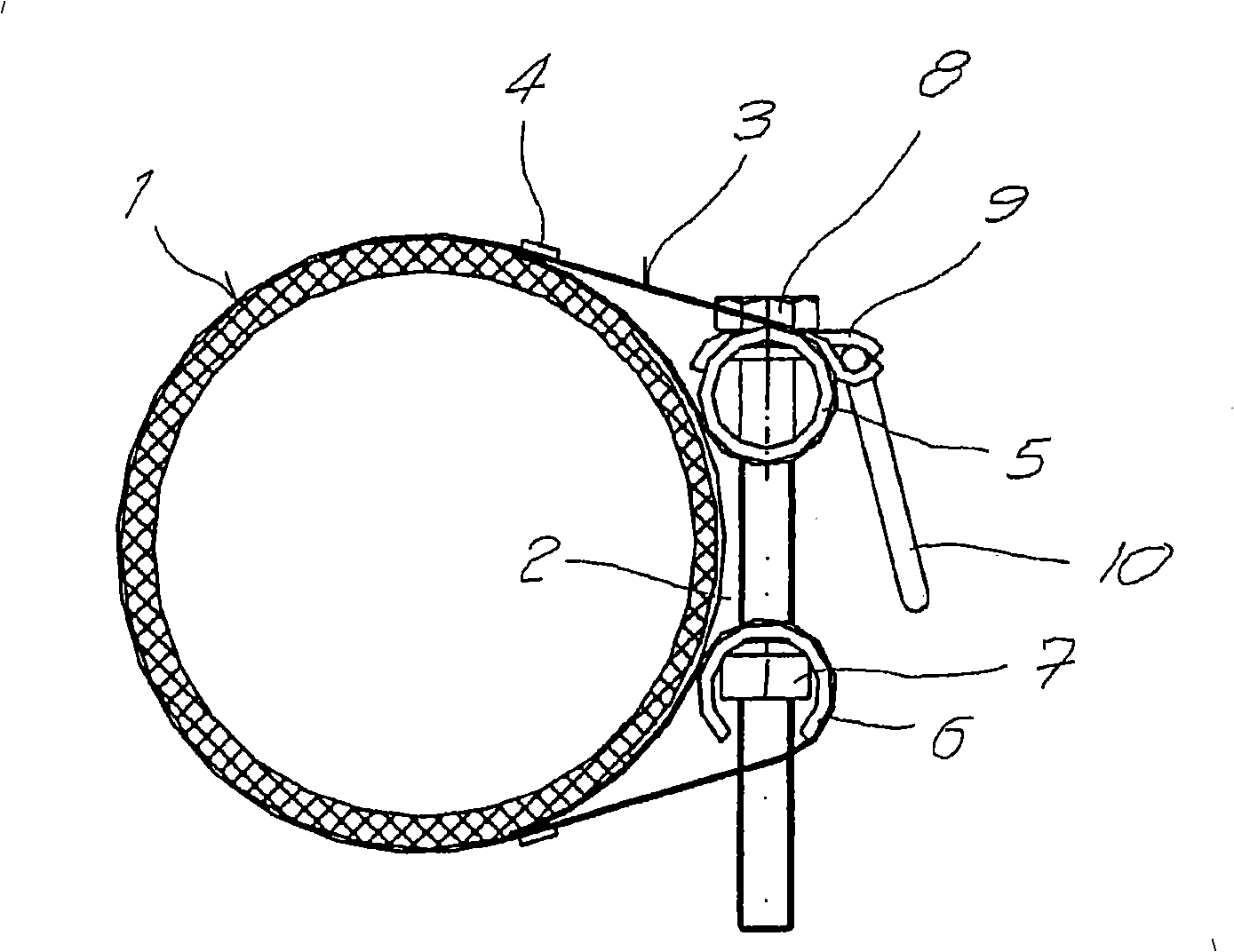
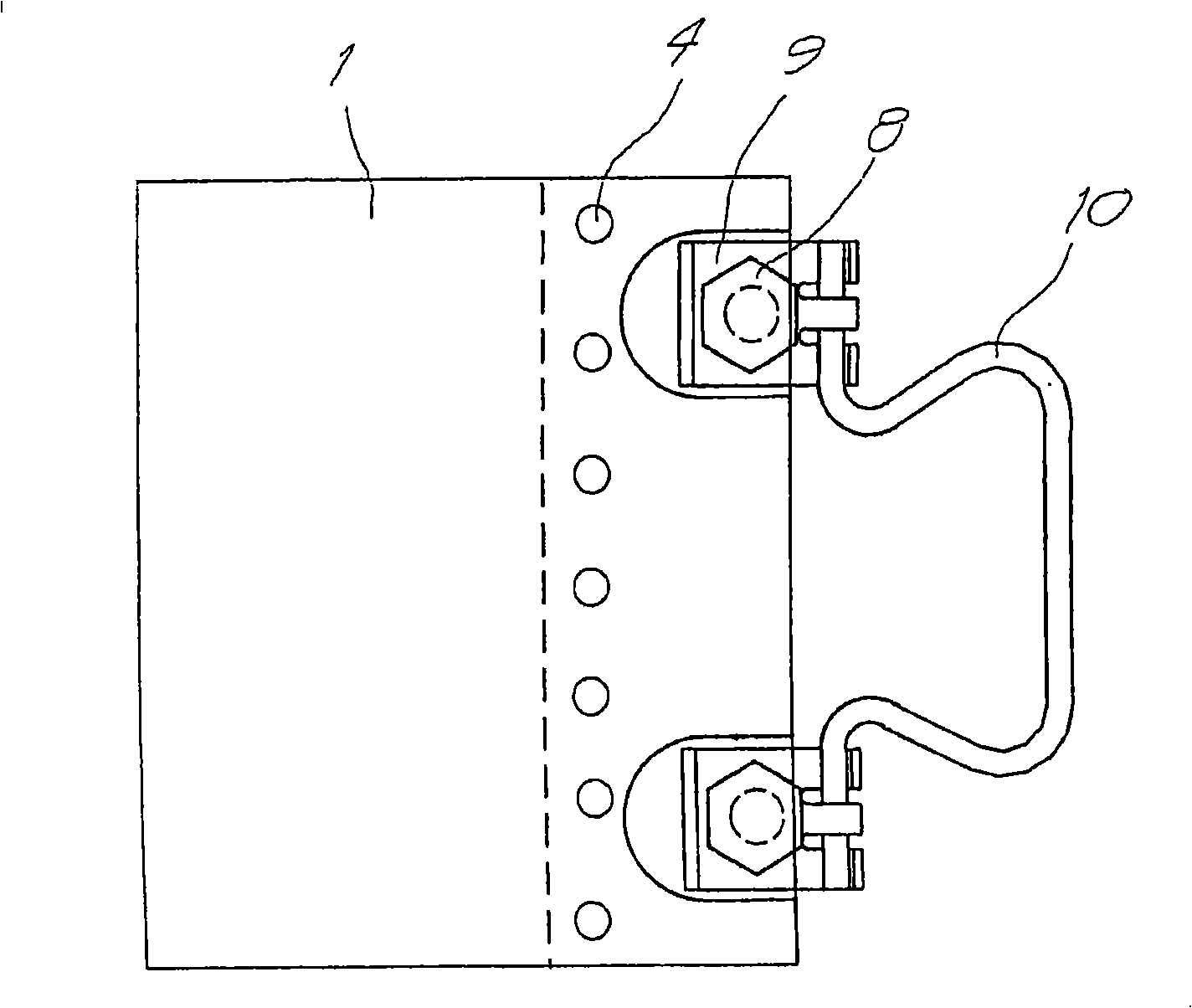
[0029] figure 1 The clamping clip or pipe clip shown essentially consists of a one-piece housing 1 with a longitudinal groove 2 . The ends of the housing 1 are configured as tabs 3 bent towards the inner wall. The free end of the counter-piece 3 is connected to the edge of the housing 1 via a press / joint connection 4 . In technical terms, this compression / joint connection 4 is also referred to as a "compression connection". Hollow bolts 5 and 6 are arranged in the counter piece 3 . The hollow bolt 5 is cylindrical, while the cross section of the hollow bolt 6 is C-shaped. A nut 7 is arranged in the hollow bolt 6 and is connected to the hollow bolt 6 in a positive fit. Hollow bolts 5 and 6 are traversed by fastening screws 8 . A washer 9 is arranged between the head of the fastening screw 8 and the hollow bolt 5 . The washer 9 has an elastic cloth cloth which, together with the bow-shaped handle 10 , forms a chain link. The handle 10 is thus pivotably connected to the cl...


PUM


Abstract

A pipe collar or clamp is provided with a deformable substantially cylindrical housing provided with at least one longitudinal slot. The areas of the housing (1) mutually opposite at the level of the longitudinal slot (2) are embodied in the form of bended tongues (3) which are used for receiving hollow bolts (5, 6). Said housing can be tensioned by means of tightening screws (8), which transversally extend through the hollow bolts (5, 6) and are arranged in the housing in a approximately tangential manner, and by means of nuts (7) screwable on the tightening screws. At least one tightening screw (8) is directly or indirectly connected to a handle (10) for manually prestressing that the pipe collar or clamp and / or for using the said tightening screw (8).

Description

technical field [0001] The invention relates to a clamping clip or pipe clip with a deformable, approximately cylindrical housing, a housing with at least one longitudinal groove, wherein regions of the housing lying opposite each other on the longitudinal groove are configured as A curved counter piece, wherein the counter piece is configured to receive a hollow bolt, and wherein the clamping clip or pipe clip can be arranged transversely through the hollow bolt and approximately tangentially to the housing The fastening screw and the nut that can cooperate with it in the hollow bolt are clamped. Background technique [0002] Clamping clips or pipe clips are used on the one hand to connect or repair leaking pipes and on the other hand they can be used to secure pipes in buildings or motor vehicles. In the first case, it is achieved by clamping or pipe clamps in the form of sleeve-shaped or other similarly shaped sealing rings to compress the outer wall surface of the pipel...

Claims


Application Information

Patent Timeline
Patent Type & Authority Applications(China)
IPC IPC(8): F16L33/04
CPCF16L33/04Y10T24/1441F16L21/065F16L55/172F16L21/06
Inventor 胡贝特·曼哈尔特
Owner STRAUB WERKE
Why Eureka
Try Eureka