

Heat exchange type ventilator
A technology of ventilating device and heat exchanger, which is applied to household heating, heating methods, lighting and heating equipment, etc., can solve the problems of large box 107 and it takes a long time to melt, so as to achieve miniaturization and reliable opening. The effect of closing action and saving power
- Summary
- Abstract
- Description
- Claims
- Application Information
AI Technical Summary
Problems solved by technology
Method used
Image

Examples
Embodiment approach 1
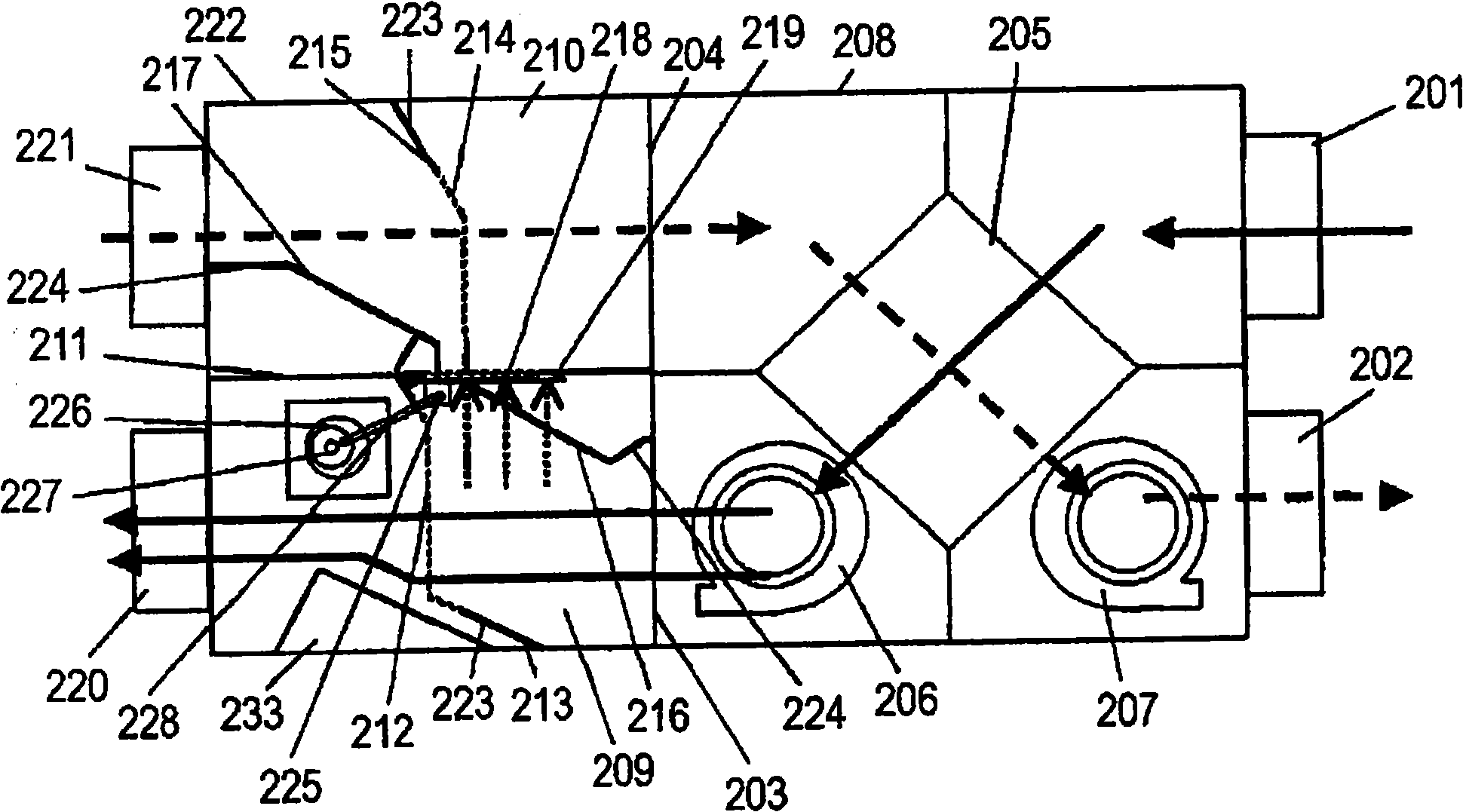
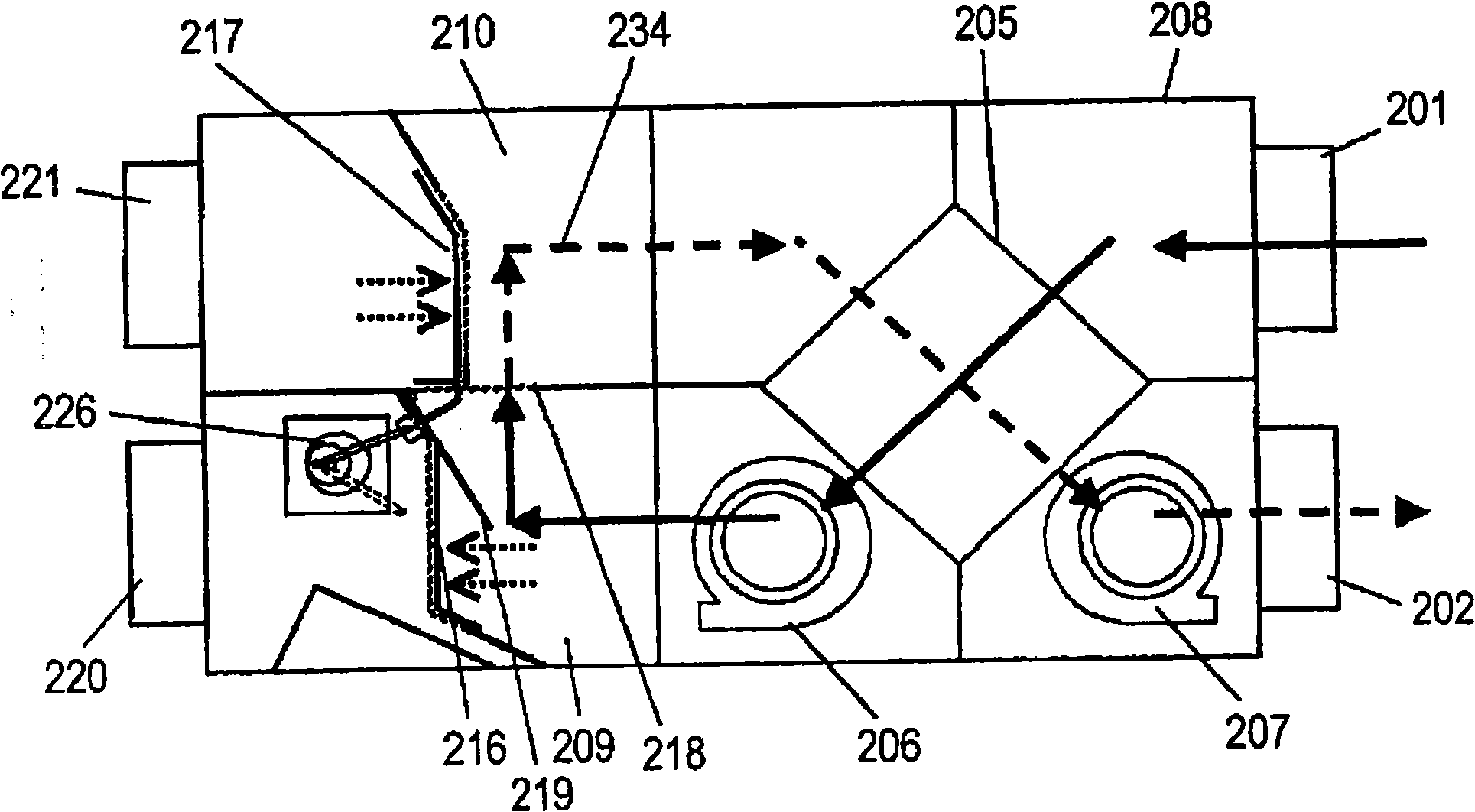
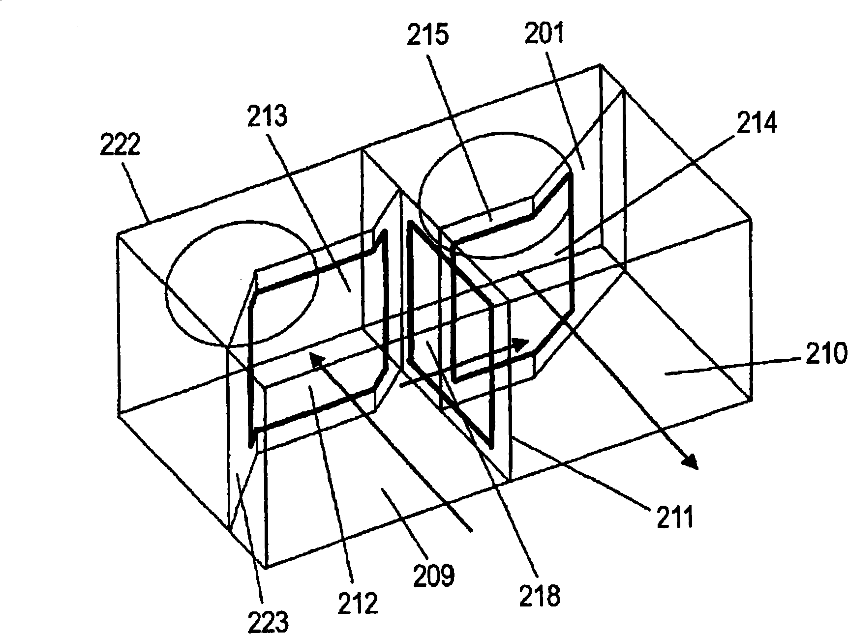
[0105] Such as Figure 1 to Figure 5 As shown, the heat exchange type ventilator according to Embodiment 1 has an indoor side exhaust port 201 and an indoor side air supply port 202 on the indoor side of one side. In addition, on the other side, an exhaust connection port 203 and an air supply connection port 204 are provided, and a heat exchanger 205 for exchanging heat between the exhaust flow from the room and the supply flow from the outside is provided inside it, and the exhaust air flow forming the exhaust air flow is formed. The blower 206 is used for exhausting the air flow.
[0106] In addition, the heat exchange type ventilator has a ventilator unit 208 provided with an air supply blower 207 for forming a supply air flow. There is also a partition for separating the exhaust flow path 209 connected to the exhaust connection port 203 of the ventilation unit 208 and the supply flow path 210 connected to the air supply connection port 204 of the ventilation unit 208 Pl...
Embodiment approach 2
[0144] refer to Figure 6 ~ Figure 8 , Embodiment 2 of the present invention will be described.
[0145] Such as Figure 6 ~ Figure 8 As shown, the heat exchange type ventilator of Embodiment 2 exchanges heat between indoor high temperature air 301 and outdoor low temperature air 302 through blower 303 and heat exchange element 304 . In addition, this heat exchange type ventilator has a bypass air passage, and the bypass air passage is composed of the following parts: a heat exchange device part 305 for performing outdoor air supply and indoor exhaust; , the low-temperature air passage 307 arriving at the heat exchange machine part 305 from the low-temperature air inlet 306; the high-temperature air passage 309 arriving at the high-temperature air exhaust port 308 from the heat exchange machine part 305; and the low-temperature air passage 307 and the high-temperature air passage 309 The opening 311 on the partition plate 310. In addition, the low-temperature air passage 30...
Embodiment approach 3
[0160] refer to Figure 9 Embodiment 3 of the present invention will be described. exist Figure 9 In , the same symbols are used for the same constituent elements as those in Embodiments 2 and 3, and descriptions thereof are omitted.
[0161] Such as Figure 9 As shown, the structure formed is: a damper 314 for the low-temperature air intake port and a damper 315 for the high-temperature air exhaust port to change the openings of the low-temperature air intake port 306, the high-temperature air discharge port 308, and the opening 311. And among the dampers 316 for the opening of the partition plate, the two dampers are integrated and their operations are interlocked.
[0162] According to the above structure, the number of motors for driving the dampers 314, 315, and 316 can be reduced, resulting in space saving and cost reduction.
[0163] In addition, the damper 314 for the low-temperature air suction port, the damper 315 for the high-temperature air discharge port, and...
PUM
 Abstract
Description
Claims
Application Information