Threading apparatus

A tapping machine and equipment connection technology, applied in the field of tapping machines, can solve problems such as working range limitation

Active Publication Date: 2010-08-25
展静
View PDF0 Cites 3 Cited by
  • Summary
  • Abstract
  • Description
  • Claims
  • Application Information

AI Technical Summary

Problems solved by technology

The above-mentioned tapping equipment can only work on the arc formed with the length of the cross arm between it and the column as the radius, and its working range is limited

Method used


Image

  • Threading apparatus
  • Threading apparatus
  • Threading apparatus

Examples


Embodiment Construction

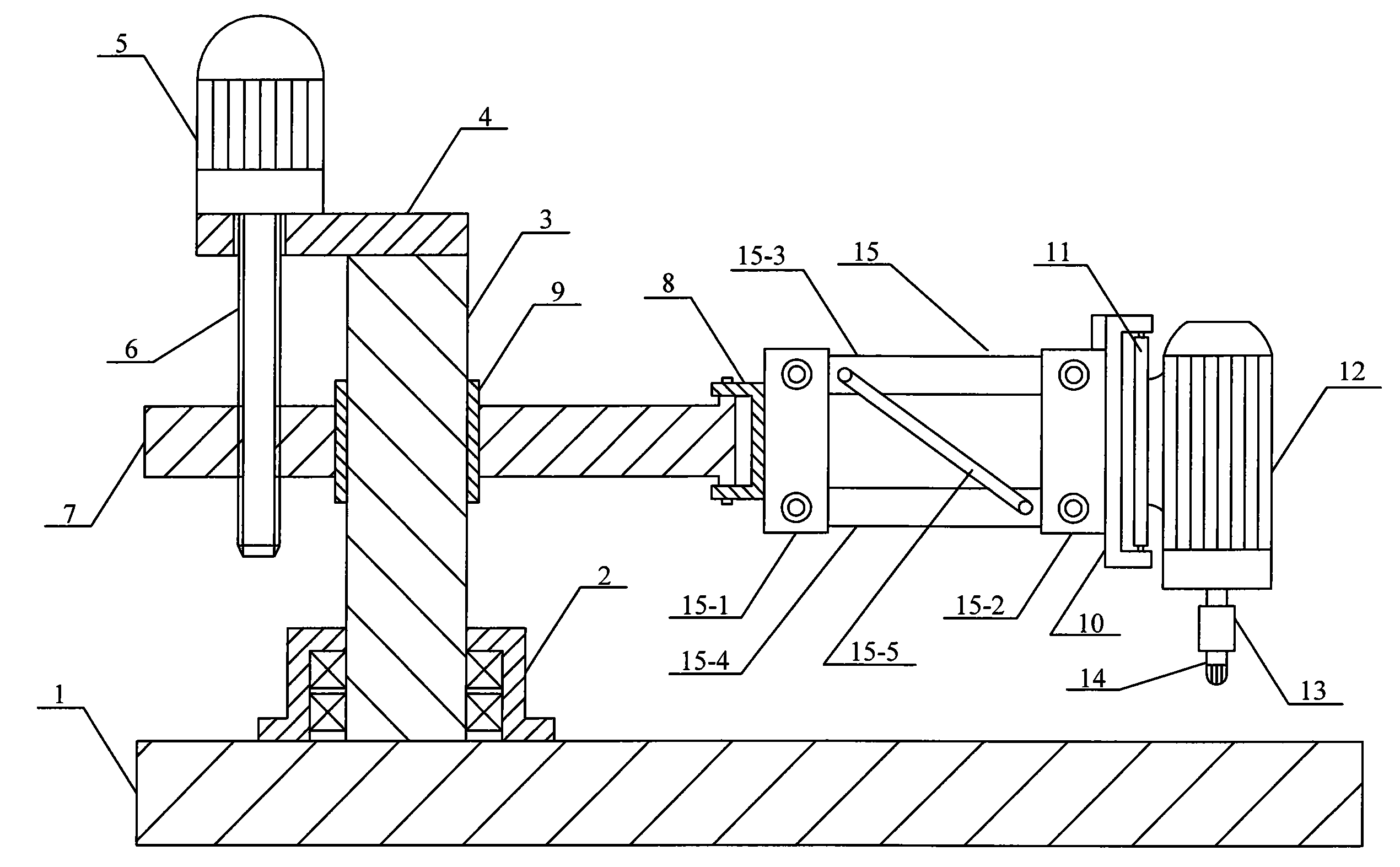
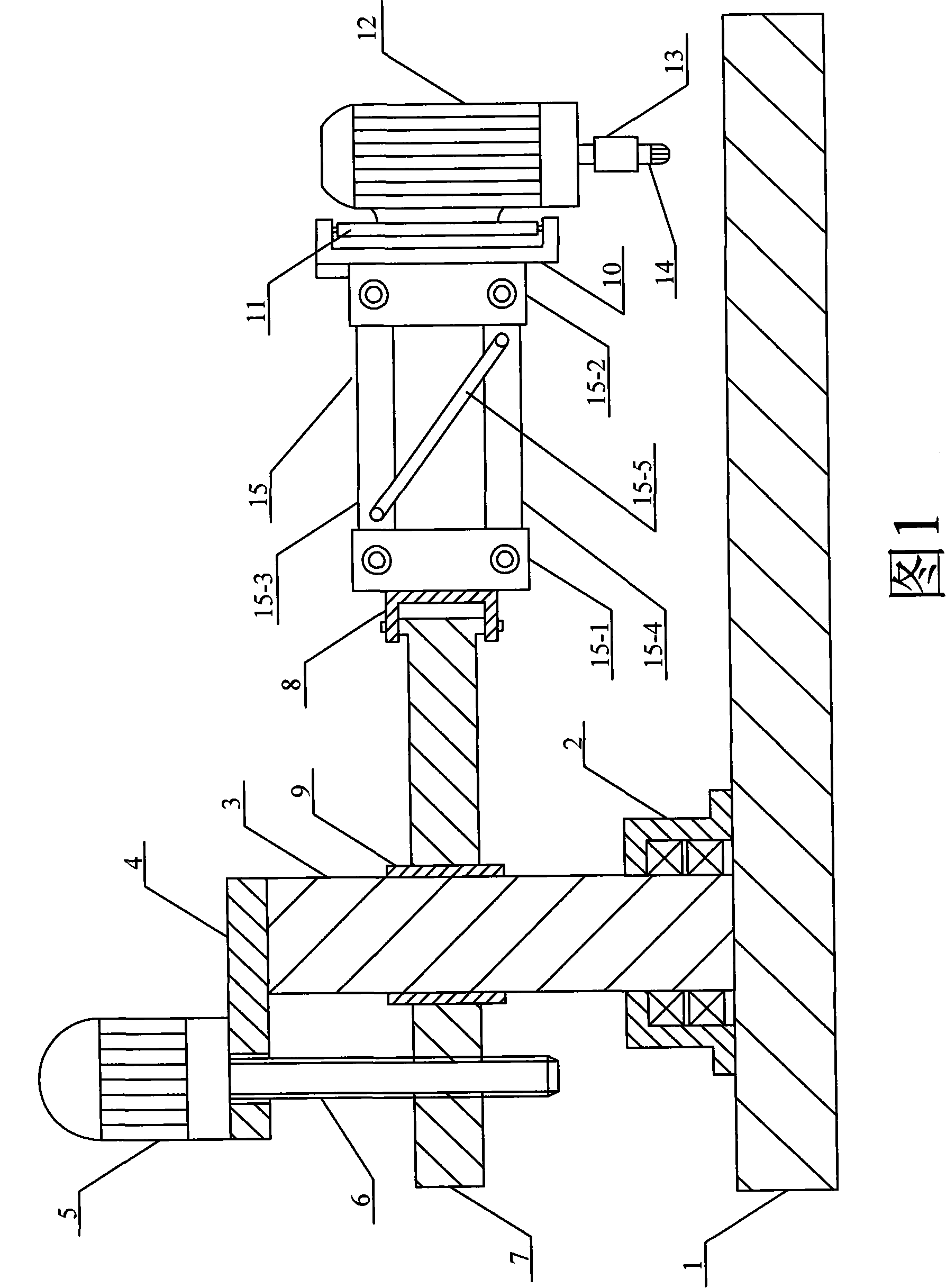
[0024] As shown in FIG. 1 , a bearing 2 is connected to the base 1 . The lower end of the column 3 is connected to the inner ring of the bearing 2 so that the column 3 can rotate around its own vertical axis; the upper end of the column 3 is connected to a horizontal connecting plate 4 .

[0025] Connect a motor 5 on the horizontal connecting plate 4, the output shaft of the said motor 5 is connected with one end of the threaded mandrel 6, and the other end of the threaded mandrel 6 runs through the horizontal connecting plate 4 and the horizontal wall on one side of the column 3 along the vertical direction. The arm 7 is threaded. The end of the cross arm 7 on the other side of the column 3 is hinged on the cross arm connecting seat 8 . The cross arm 7 is connected to the column 3 through a sliding sleeve 9 .

[0026] In addition, it also includes a tapping device connection base 10 and a tapping device connection plate 11 . A vertical side of the tapping device connection...


PUM


Abstract

The invention discloses a tapping machine with high tapping efficiency in the technical field of tapping devices, the tapping machine can make all directional tapping for work pieces under the condition of not moving the work pieces. The tapping machine comprises a base, an upright column, a cross arm, a tapping device and a connecting arm; wherein, the lower end of the upright column which is horizontally connected with the cross arm is connected with the base by a bearing; one end of the connecting arm is articulated with one end of the cross arm so as to change the horizontal separation angle between the connecting arm and the cross arm; the other end of the connecting arm is connected with the tapping device.

Description

technical field [0001] The invention belongs to the technical field of tapping equipment, and in particular relates to a tapping machine. Background technique [0002] Existing tapping machine is usually made up of base, column, cross arm and tapping equipment. The lower end of the column is connected to the base through a bearing, the cross arm is horizontally connected to the column, and the tapping device is connected to one end of the cross arm. Above-mentioned tapping equipment can only work on the circular arc formed with the cross arm length between it and the column as the radius, and its working range is limited. For example, when it is necessary to tap in the area within the above-mentioned arc, the workpiece must be moved so that the tapping position on the workpiece is aligned with the tapping device, and then the tapping operation is performed. Contents of the invention [0003] The technical problem to be solved by the present invention is to provide a tapp...

Claims


Application Information

Patent Timeline
Patent Type & Authority Patents(China)
IPC IPC(8): B23G1/18B23G1/44B23G1/48
Inventor 展静
Owner 展静
Why Eureka
Try Eureka