Crankcase ventilation apparatus of V type engine

A crankcase ventilation and engine technology, applied in crankcase ventilation, engine components, machines/engines, etc., can solve problems such as uneven pressure, blue smoke from burning engine oil, complex structure, etc., to improve the removal effect and lengthen the passing path , Improve the effect of safety performance

Active Publication Date: 2008-12-24
WUXI KIPOR POWER CO LTD
View PDF0 Cites 5 Cited by
  • Summary
  • Abstract
  • Description
  • Claims
  • Application Information

AI Technical Summary

Problems solved by technology

[0003] In order to prevent excessive pressure in the rocker chamber, one traditional solution is to install a molded breather part on the crankcase cover, and connect the gas coming out of the breather to the intake regulator box. This method has a complicated structure And because it is not installed at the highest point, the effect is not obvious. Another method is to arrange traditional plastic ball respirators in the left and right cylinder head covers, and directly pass the gas coming out of the respirator to the intake ports of each cylinder. The plastic ball whistler uses its own gravity to reset, it is effective on in-line engines, but it is not effective on V-type engines because the cylinder is tilted at an angle
The third is to install a modular respirator in one of the left and right cylinder head covers, and pass the gas out of the respirator to the intake port or the pressure-stabilizing box of this cylinder, and the other cylinder has no respirator and To reduce costs, although the entire crankcase is connected to the rocker chambers of the two cylinders, because one cylinder has a breather and the other cylinder does not, the pressure in the rocker chambers of the two cylinders will still be uneven, so that there is no breather The pressure of the cylinder is relatively high, and there is more oil mist, which enters the combustion chamber of this cylinder through the gap of the valve guide oil seal, causing the cylinder to burn oil and emit blue smoke, and the combustion of engine oil will cause harm to both the operator and the engine.

Method used


Image

  • Crankcase ventilation apparatus of V type engine
  • Crankcase ventilation apparatus of V type engine
  • Crankcase ventilation apparatus of V type engine

Examples


Embodiment Construction

[0016] The present invention will be further described below in conjunction with the embodiment in the accompanying drawings:

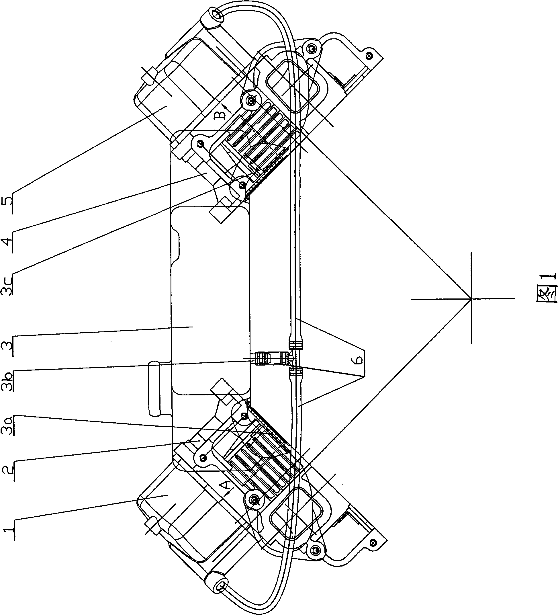
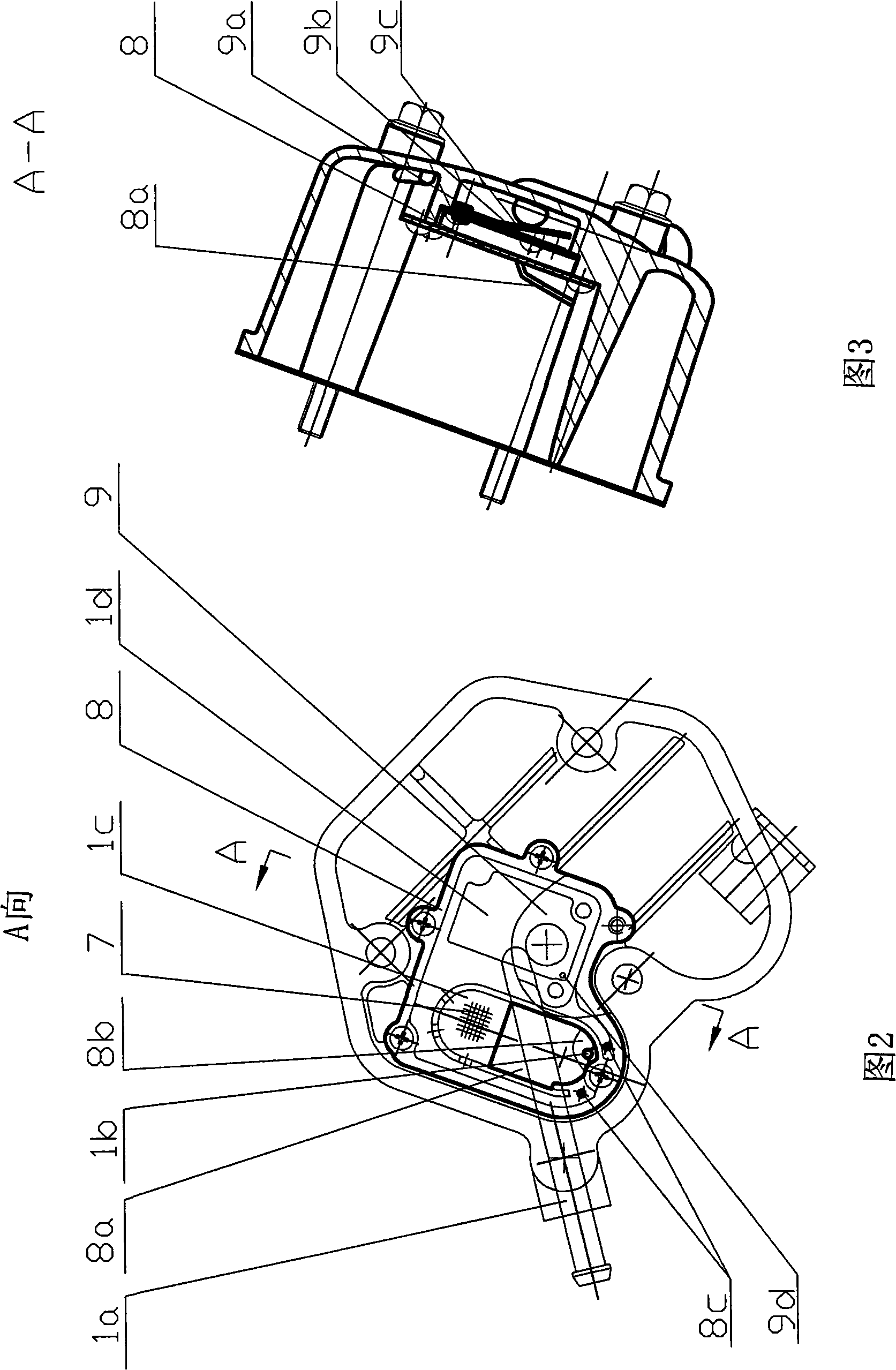
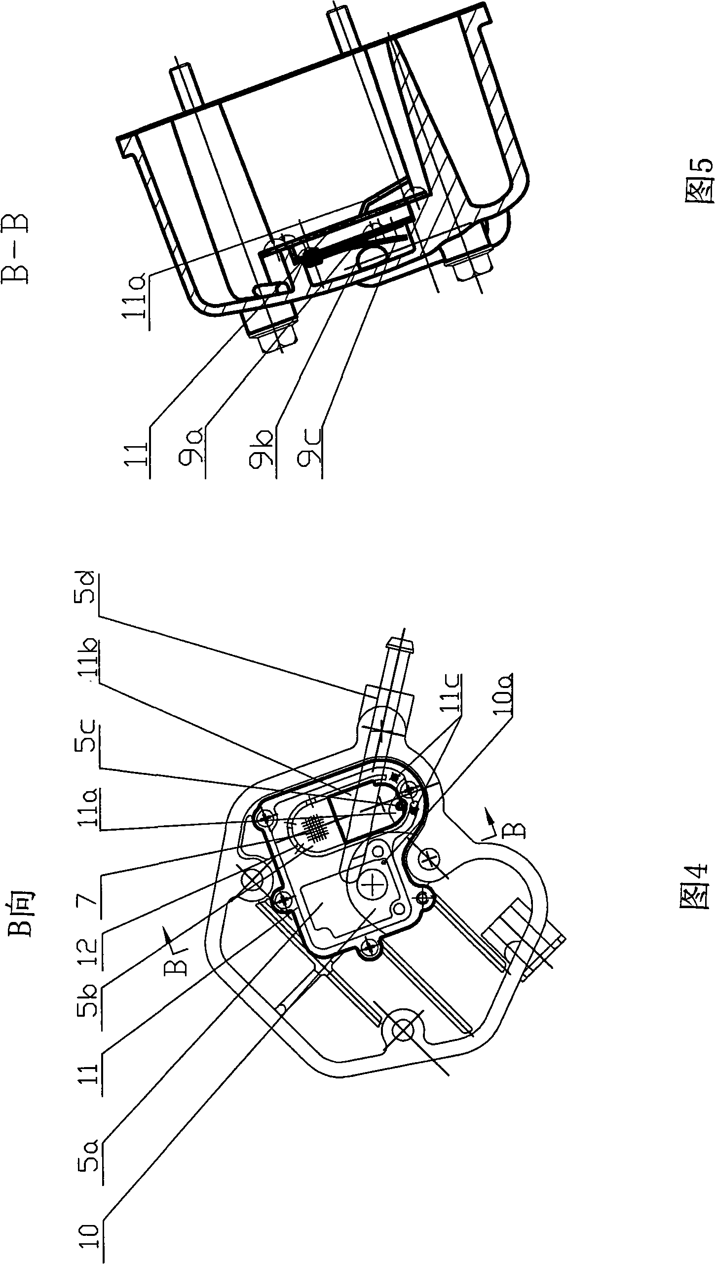
[0017] As shown in Figures 1 to 5, it includes: left and right cylinder head covers 1, 5 (pipeline channels 1a, 5d, ejector rods 1b, 5c, oil-gas separation chambers 1c, 5b, control switch chambers 1d, 5a), left , right cylinder head 2, 4, surge tank part 3 (bottom joint 3b, intake connecting pipe 3a, 3c), pipeline system 6, filter screen 7, oil baffle 8, 11 (oil baffle support 8a, 11b, oil and gas inlets 8b, 11a of the oil baffle, oil return holes 8c, 11c of the oil baffle), check valve parts 9, 10 (breather spring 9b, spring plate 9c, cover plate 9a, oil return hole 9d, 10a) etc.

[0018] The present invention mainly adopts to install the intake pressure stabilizing box part 3 on the air intake side of the left and right cylinder heads 2 and 4 arranged in a V shape, and install the left and right cylinder head covers on the left and right cylinder h...


PUM


Abstract

The invention relates to a device for ventilating a crankcase of a V-type engine belonging to the power device technical field. The device mainly comprises a left cylinder head, a right cylinder head, a left cylinder head cover, a right cylinder head, and an air inlet pressure stabilizing chamber. The device is characterized in that the insides of the left cylinder head cover and the right cylinder head cover are provided with oil baffle plates, and oil-gas separation chambers and control switch chambers are formed by isolating the oil baffle plates, the insides of the control switch chambers are provided with one-way valves, the pipe passages are arranged inside the control switch chambers; after the pipe passages of the two head covers are communicated with each other, the pipe passages of the two head covers are connected to the bottom of the air inlet pressure stabilizing chamber, template one-way valves are respectively arranged inside the two head covers, and the pipe passages of the two head covers are connected to the bottom of the air inlet pressure stabilizing chamber after the pipe passages of the two head covers are communicated with each other. The device can guaranty pressure in the crankcase to be reasonable and stable and a passing route of an oil mist is long when removing the surplus gas in the crankcase, thereby improving removal effect for the oil mist, preventing the overmuch oil mist from entering the combustion chamber, reducing engine oil consumption, and improving safety performance of the whole engine.

Description

technical field [0001] The invention relates to a crankcase ventilation device for a V-type engine, which can keep the pressure in the crankcase reasonable and stable, and prevent a large amount of oil mist from being sucked into the combustion chamber when exhausting excess gas in the crankcase, so as to improve the performance of the entire engine. The safety performance belongs to the technical field of power devices. Background technique [0002] In a general engine, the rocker arm that controls the intake and exhaust valves is located on the cylinder head. In order to keep the rocker arm parts in a sealed space, a hollow shell is fixed and sealed on the cylinder head. This hollow shell is called Cylinder cover. The space formed by the cylinder head cover and the cylinder head is called the rocker chamber. The rocker arm chamber communicates with the crankcase of the engine, so when the engine is running, the gas leaking from the gap between the piston and the cylinder...

Claims


Application Information

Patent Timeline
Patent Type & Authority Applications(China)
IPC IPC(8): F01M13/04
Inventor 肖亨琳
Owner WUXI KIPOR POWER CO LTD
Why Eureka
Try Eureka