Compressed liquefied gas charging system

A technology of liquefied gas and gas cylinders, applied in gas/liquid distribution and storage, container filling methods, equipment loaded into pressure vessels, etc., can solve the problem of not being able to get rid of the backward working mode of mechanical scales, the inability to distinguish and eliminate interference forces, and knife edges Susceptible to moisture, rust or corrosion, etc., to achieve the effect of reducing filling personnel, automatically adjusting filling flow, and reducing labor intensity of workers

Inactive Publication Date: 2011-04-13
广西柳州海湾恒日化工气体有限公司
View PDF0 Cites 0 Cited by
  • Summary
  • Abstract
  • Description
  • Claims
  • Application Information

AI Technical Summary

Problems solved by technology

The mechanical quantitative filling device is a simple mechanical device that closes the valve of the gas valve switch only by touching the gas valve switch when the beam beam is lifted. Its function is too simple to get rid of the backward working mode of the mechanical scale. The weighing process is cumbersome, the exposed knife edge is easy to be damp, rusted or corroded, which will affect the accuracy of the weighing, and it needs professional maintenance and inspection before it can continue to be used.
Although the electronic scale quantitative filling device can achieve the purpose of convenient weighing and simple operation, it also has the following disadvantages: 1. It cannot distinguish and eliminate the disturbing force that is easily generated during the filling process, such as the leakage of the fixture joint The force generated by clapping the chuck will lead to early closure caused by the virtual weighing fixed value; 2. It only has the function control of quantitative filling of a single gas cylinder

Method used


Image

  • Compressed liquefied gas charging system
  • Compressed liquefied gas charging system
  • Compressed liquefied gas charging system

Examples


Embodiment Construction

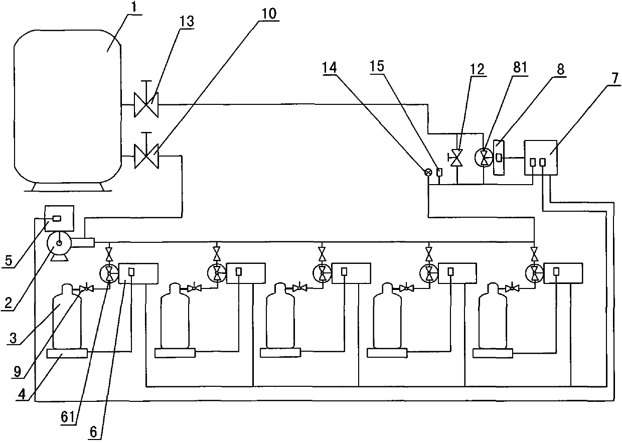
[0026] Such as Figure 1 to Figure 5 As shown, the compressed liquefied gas filling system of the present invention includes a liquid storage tank 1, a filling pump 2, a gas cylinder 3, a filling platform 4, an automatic flow adjustment device 5, an intelligent quantitative filling device 6, an adjustment control center device 7 and Automatic pressure regulator 8.

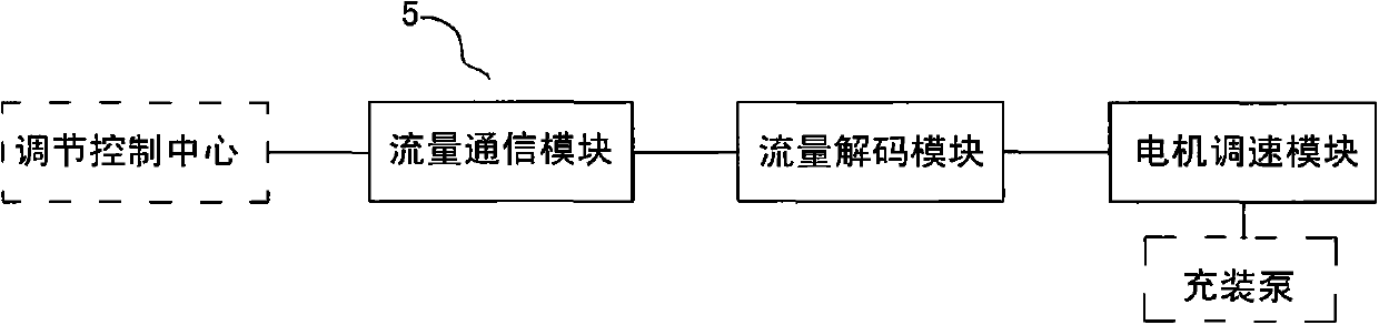
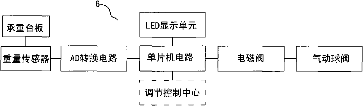
[0027] The filling pump 2 is connected to the liquid storage tank 1 through a pipeline, the gas cylinder 3 is placed on the filling platform 4, and the gas cylinder 3 is connected to the filling pump 2 through a pipeline. The filling pump 2 is connected with an automatic flow adjustment device 5 that can automatically control the flow of the filling pump. An intelligent quantitative filling device 6 is connected between the gas cylinder 3 and the filling pump 2. The automatic flow adjustment device 5 And the intelligent quantitative filling device 6 is also connected to the adjustment control center device 7 throu...


PUM


Abstract

The invention relates to a compressed liquefied gas charging system, belonging to the liquefied gas charging field. The compressed liquefied gas charging system comprises a liquid storage tank, a charging pump, a gas bottle and a charging platform, wherein the charging pump is connected with the liquid storage tank by a pipeline; the gas bottle is arranged on the charging platform and is connected with the charging pump by the pipeline; the charging pump is connected with an automatic flow rate adjusting device used for automatically controlling the flow rate of the charging pump; an intelligent quantifying charging device used for automatically controlling the charging quantity is arranged between the gas bottle and the charging pump; the compressed liquefied gas charging system also comprises an adjusting control center device and an automatic pressure adjusting device; the automatic flow rate adjusting device and the intelligent quantifying charging device are also respectively connected with the adjusting control center device by a control circuit; and one end of the automatic pressure adjusting device is connected with the adjusting control center device, and the other end thereof is connected with the liquid storage tank. By adopting the structure, the compressed liquefied gas charging system has the advantages of full-automatic control, accurate charging quantity, low cost, safety, long service life and the like.

Description

【Technical field】 [0001] The invention relates to the technical field of filling liquefied gas, in particular to the technical field of filling compressed liquefied gas. 【Background technique】 [0002] Liquefied petroleum gas has a high calorific value, takes up little space for storage, and is easy to use, so it is very popular among the people. However, liquefied gas is flammable, explosive, and volatile, and its storage and transportation are greatly restricted. Usually, a large liquefied gas tank is installed at a liquefied gas station, and the large liquefied gas tank is filled with liquefied gas through a liquefied gas filling device. Fill into the user's liquefied gas cylinder. At present, there are two kinds of liquefied gas filling devices commonly used in the industry, namely: mechanical quantitative filling device and electronic scale quantitative filling device. The mechanical quantitative filling device is a simple mechanical device that closes the valve of th...

Claims


Application Information

Patent Timeline
Patent Type & Authority Patents(China)
IPC IPC(8): F17C5/02F17C13/02F17C13/04
Inventor 翁跃平朱声强
Owner 广西柳州海湾恒日化工气体有限公司
Why Eureka
Try Eureka