

Syringe marking template
- Summary
- Abstract
- Description
- Claims
- Application Information
AI Technical Summary
Benefits of technology
Problems solved by technology
Method used
Image


Examples
Embodiment Construction
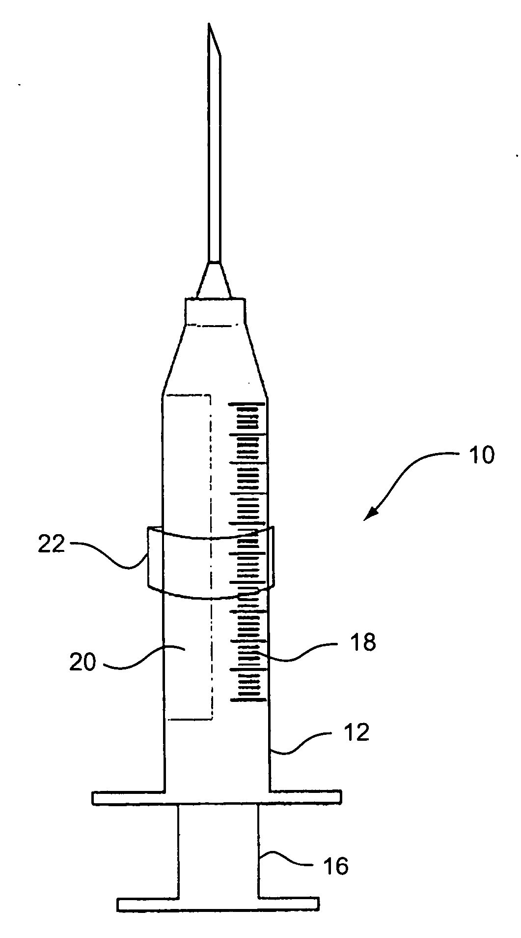
[0024] Referring to the drawings particularly to FIG. 1, there is illustrated a typical syringe generally designated 10 including a barrel 12, a needle or cannula 14 on the distal end of the barrel and a plunger 16 slidable within the barrel. Syringe 10 is of a conventional construction and includes index markings 18 on the barrel as well as a contrasting color marking or stripe 20 coextensive with the index markings 18 along the opposite side of the barrel from the index markings. The contrast marking or stripe 20 is disclosed in U.S. Pat. No. 6,315,760, incorporated herein by reference.
[0025] As the above discussion indicates, the index markings 18 particularly on small diameter syringes e.g. 1 ml., 0.5 ml. or 0.3 ml. are very difficult to see and it is therefore difficult align the plunger 16 accurately to ensure accurate filling with medicament and therefore correct dose delivery to the patient.
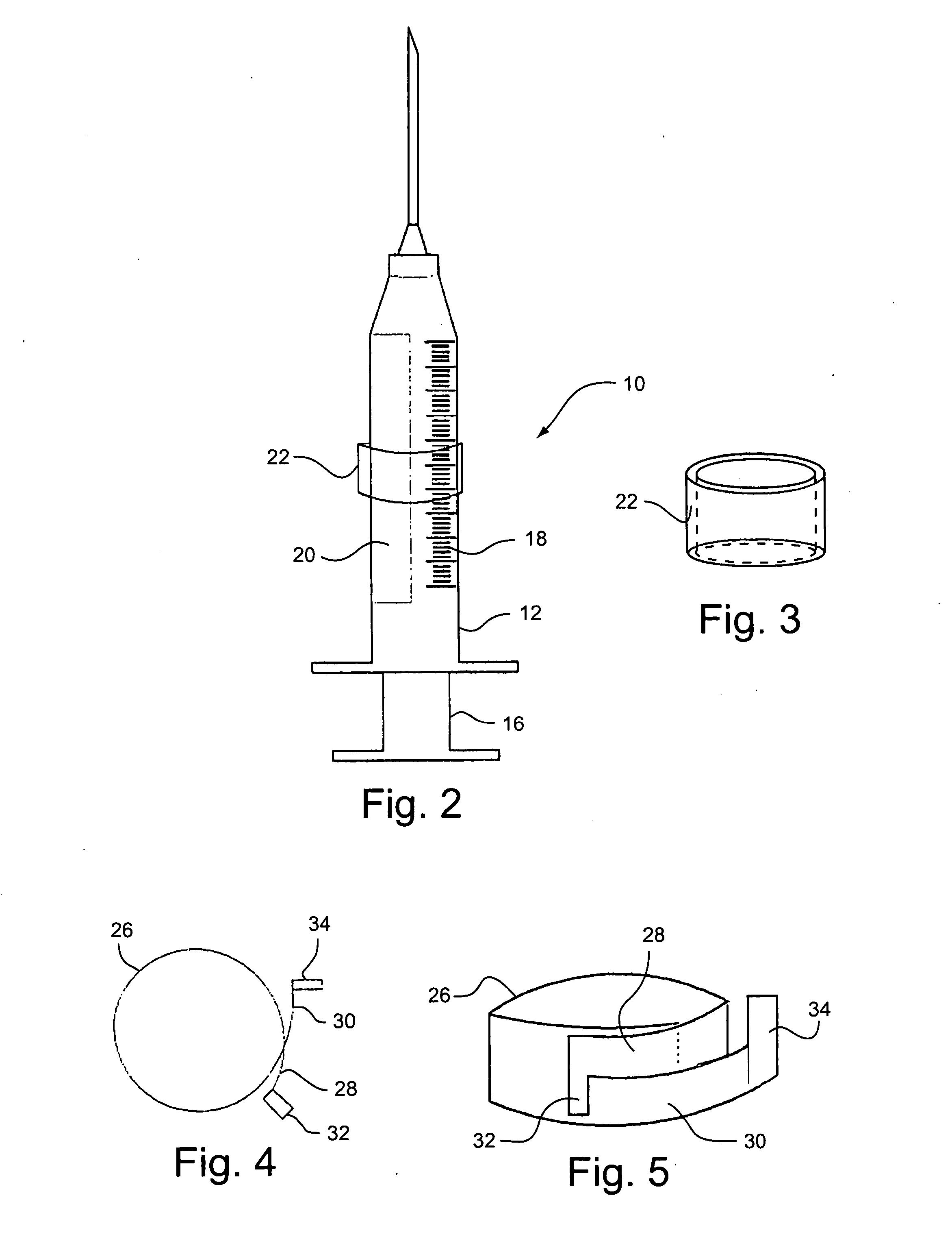
[0026] Referring to FIG. 2, there is provided a custom dosage template or collar 22...
PUM
 Abstract
Description
Claims
Application Information