

Mechanically-releasing spring ring system
A spring coil and mechanical technology, which is applied in the field of medical devices, can solve the problems of no spring coil, inability to observe the release of the spring coil intuitively, inconvenience for the operator, etc., so as to reduce the manufacturing and processing cost, avoid uneven force, and simplify the manufacturing process. Effect
- Summary
- Abstract
- Description
- Claims
- Application Information
AI Technical Summary
Problems solved by technology
Method used
Image

Examples
Embodiment 1
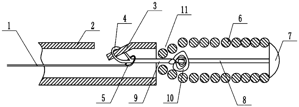
[0029] Basic as attached figure 1 Shown: figure 1 The left end in the middle is the proximal end, which refers to the end of the surgical operation, figure 1 The right end is the distal end, which refers to the end away from the operator.
[0030] The mechanical release coil system includes the push rod 2, the spring coil 6 and the connection assembly. The improvement in this embodiment lies in the push rod 2 and the connection assembly. For the connection assembly, it can be a complete wire or a plurality of wires. connected, the spring ring 6 is sleeved on the connection assembly, and the connection assembly is located in the part of the spring ring 6 and is provided with a protruding part near the proximal end of the spring coil 6, and the protruding part can be glued on the connection assembly Blocks made of plastic, metal or protrusions made of other materials are specifically combined in this embodiment. The connection assembly in this embodiment uses an anti-untwistin...
Embodiment 2
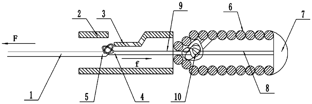
[0041] combine Figure 4 As shown, this embodiment is improved on the basis of Embodiment 1. The far end of the push rod 2 is divided into two sections. The right end of the left part of the push rod 2 is a tapered surface. The elastic part 16 in the example is a spring tube, the proximal end of the spring tube is connected to one end of the tapered surface of the push rod 2, the distal end of the spring tube is connected to the lumen containing the hook 3 on the push rod 2, and the far end of the guide wire 1 is pulled. Both the end and the elastic portion 16 are provided with an X-ray-opaque developing mark 15 .
[0042] In this embodiment, during the callback process of the spring ring 6, when the release point is subjected to a pulling force to the far end, since the collar 4 passes through the draw ring 5 and hangs on the hook 3 to form a pin connection (the hook 3 is equivalent to a pin), The pulling force to the distal end of the spring coil 6 will act on the pulling g...
Embodiment 3
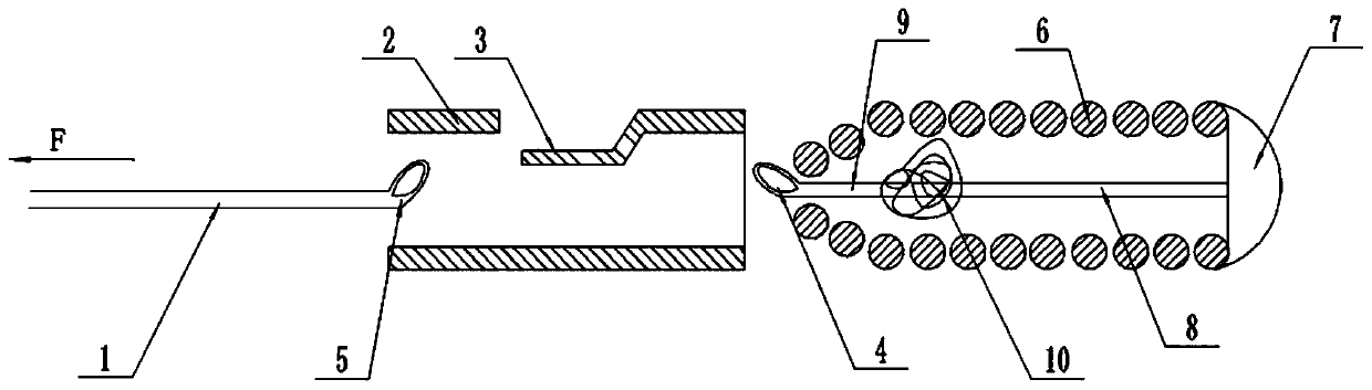
[0045] combine Figure 5 As shown, the present embodiment is improved on the basis of Embodiment 1. An upper baffle 12 is integrally formed on the top of the hook 3, and a lower baffle 14 is welded on the notch end of the push rod 2 provided with the hook 3. The plate 14 is an elastically deformable metal shrapnel (such as a leaf spring, etc.), and a pull cord 13 is bolted to the pulling guide wire 1 , and the pull cord 13 is bolted to the bottom end of the lower baffle plate 14 . In this way, when the collar 4 is positioned on the hook 3, the top of the collar 4 is blocked by the upper baffle 12, and the lower end of the collar 4 is blocked by the lower baffle 14, so that the collar 4 is positioned on the hook 3, avoiding the The ring 4 slides upwards and disengages from the hook 3 under the rightward pulling force of the connecting piece 9, while avoiding that the connecting piece 9 is relatively loose, and the collar 4 is separated from the bottom end of the hook 3.
[004...
PUM
 Abstract
Description
Claims
Application Information