
Mobile fluid product filling system with fast setup

a technology of fluid product and filling system, which is applied in liquid handling, packaging goods, transportation and packaging, etc., can solve the problems of limited filling accuracy, unsuitability of volumetric filling, and limited filling speed, so as to reduce maintenance and increase safety, the effect of fast shut-down and start-up tim

Inactive Publication Date: 2003-07-22
IDEAL MFG & SALES
View PDF16 Cites 15 Cited by
  • Summary
  • Abstract
  • Description
  • Claims
  • Application Information

AI Technical Summary

Benefits of technology

The foregoing arrangement has exceptionally fast shut-down and start-up time because a filling unit only needs to be put in the ready-to-fill position, with its filling head situated over the filling position, in order to establish communications between the filling unit and the filling station. No connections between the filling unit and filling station are required. This lack of connections also reduces maintenance and increases safety, since there need not be any pneumatic or electric lines extending between the filling unit and filling station. Such lines can cause tripping or which can easily be damaged by traffic adjacent to the filling operations, either while they are connected or when they are disconnected and trailing from the filling unit and / or filling station. It is also notable that when the invention is used in lieu of filling systems wherein pneumatic communications conduits are connected between the filling unit and filling system, the invention provides more accurate filling. This is because pneumatic communications signals are subject to degradation and delay, as they may only travel at the speed of sound, and a portion of the signal is lost owing to expansion of flexible pneumatic conduits (particularly in longer conduits). Where pneumatics are used in the invention, such degradation and delay is greatly reduced because the length of any pneumatic circuits allowing communication between the filling unit and filling station are interrupted by the switching member and dispensing switch. For example, as compared to prior filling systems wherein a pneumatic communication line extended from the filling unit to a container fill sensor at the filling station, the invention allows the lengths of the pneumatic lines on the filling unit side and the filling station side to be reduced by as much as one-half.

Problems solved by technology

Volumetric filling is subject to the disadvantages that filling accuracy is limited by the accuracy of the control of the chamber volume, and filling speed is limited by the time necessary for refilling the chamber.
Volumetric filling is also unsuitable where one wishes to fill a container with a desired weight of fluid: variations in fluid density will lead to variations in the weight of the fluid dispensed from the chamber and result in different weights being dispensed into different containers; viscous fluids may stick to the dispensing apparatus and result in incomplete dispensation; and so forth.
However, time-metered filling is subject to inaccuracy unless a constant flow rate is precisely maintained, and this is particularly difficult to attain where flow rates are high.
Additionally, time-metered filling is subject to the same disadvantages as volumetric filling in that variations in fluid density will result in different weights of fluid being dispensed to different containers, even if the volume of the dispensed fluid remains relatively constant from container to container.
First, the weight sensors and feedback apparata are quite costly if any reasonable degree of accuracy is required.
Second, the filling time per container tends to be significantly longer owing to the weight feedback; sensitive weight sensors need time to "settle" prior to giving accurate weight readings, and additionally slower filling rates must often be used since the flow must be cut off precisely at or slightly before the time the desired weight is reached, or overshoot will result in an overweight container with product "give-away".
Such semiautomatic filling systems, while useful, are not well suited for high production speeds and significant output of filled containers.
Automatic filling systems are necessarily more complex because the extent of filling of the containers must be measured, either gravimetrically, volumetrically, or by other methods, and the filling units which effect filling must communicate with the conveyors to synchronize the filling operation with the container supply.
One disadvantage of the foregoing filling systems is their requirement that a communications connection be established between the filling unit and the filling station in order to allow filling to be synchronized with the container supply: Sauer requires the chain of the filling unit be connected to the filling station, and the filling systems of the Roberts et al. type require that the pneumatic lines of the filling units be connected to the filling station and its weight sensors.
These connections may take time to establish and verify; consider, for example, that the chain of Sauer must be attached to the sprocket at a correct location, or else the synchronization between the filling unit and conveyor will be improperly timed.
Additionally, the mechanical and pneumatic connections of Sauer and Roberts et al., which essentially have the nature of "umbilicals" which extend between the filling unit and filling station, can provide a tripping hazard, are subject to damage during transport of the filling units or when activities occur in the filling environment, and / or can be fouled (e.g., by product spills).
Damage and / or fouling can make connection between the filling units and filling stations difficult (or impossible), or it may interfere with proper synchronization.
However, such electronic communications are subject to noise interference from other electronics in the filling system's environment, and additionally the components needed to enable such communications are prohibitively expensive (at the time this document was filed as a patent application).
The same is true of sonic / ultrasonic communications, which are even more subject to noise interference.
However, while optical communications components have reasonable cost, they are particularly subject to fouling by spilled product: once spilled product distorts or obscures the light beam which provides the filling signal, the system becomes inoperative or malfunctions.
An additional problem with all of the foregoing modes of communication is that they generally require electronics for operation, and it is often desirable to avoid electronics in filling environments wherein flammable materials are used.

Method used


Image

  • Mobile fluid product filling system with fast setup
  • Mobile fluid product filling system with fast setup

Examples


Embodiment Construction

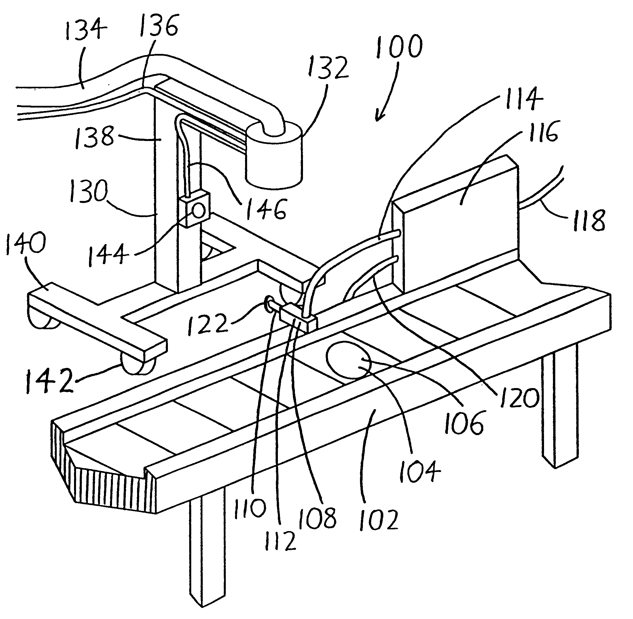
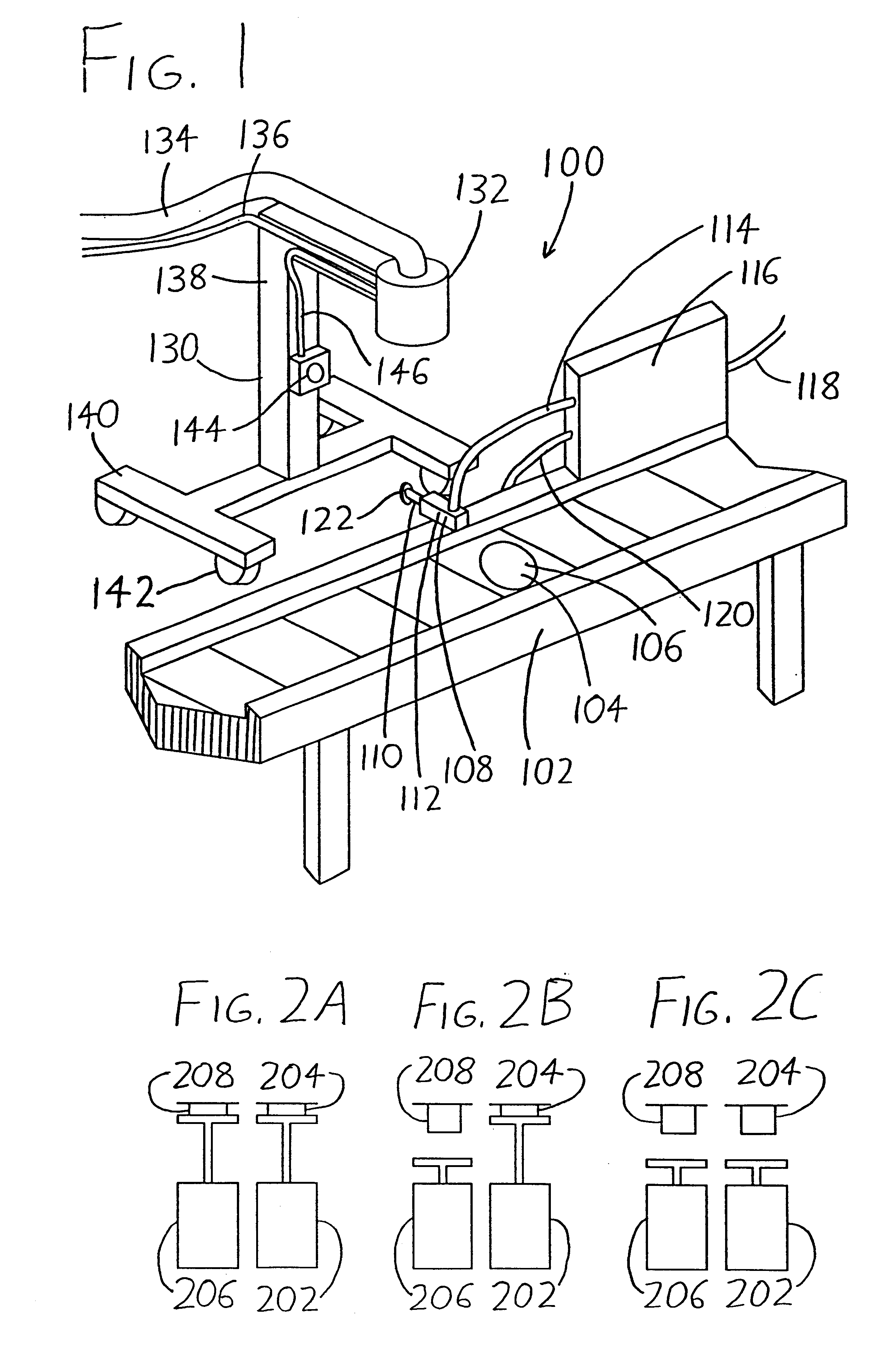
An exemplary preferred version of the invention is illustrated in FIG. 1, wherein a filling system 100 is shown with a filling station 102 (the filling station 102 in this case being provided by a conveyor) and a filling unit 130. The filling station 102 has a filling position 104 at which a container traveling on the conveyor is to be filled with fluid product. A container fill sensor 106 (e.g., a weight sensor such as a load cell or digital scale) is situated at the filling position 104 so that it may detect the degree to which a container situated at the filling position 104 is filled with fluid product. A movable switching member 108 is also provided on the filling station 102, preferably at a point adjacent to the filling position 104 and at or near one of the boundaries of the filling station 102 (in the filling system 100 of FIG. 1, at the edge of the conveyor of the filling station 102). The switching member 108 is shown with a rod 110 which is driven by a pneumatic cylinder...


PUM

PropertyMeasurementUnit
volumeaaaaaaaaaa
filling speedaaaaaaaaaa
weightaaaaaaaaaa

Abstract

A fluid filling system has a filling unit which is repositionable with respect to a filling station. The filling unit includes a filling head and a dispensing switch. The filling station has a filling position at which a container may be placed for filling with fluid. A container fill sensor is provided at the filling position so that it may detect the degree to which a container is filled. A movable switching member is also provided on the filling station, and it communicates with the container fill sensor and moves to different positions in accordance with the degree to which a container at the filling position is filled. The filling unit is repositionable with respect to the filling station so that the filling unit may be situated adjacent the filling station with its filling head situated over the filling position, or may be moved to allow the filling unit to rest at other locations. When the filling unit is resting adjacent the filling station with its filling head situated over the filling position (i.e., when it is in the ready-to-fill position), the switching member and dispensing switch are adjacently situated between the filling unit and filling station so that the switching member may actuate the dispensing switch. Thus, when the container fill sensor detects that container filling is to occur (or is to cease), the switching member is actuated, which in turn actuates the dispensing switch to change the filling head between its filling state and its nonflow state in accordance with the filling detected by the container fill sensor.

Description

This disclosure concerns an invention relating generally to methods and apparata for fluid dispensation, i.e., the dispensation of liquids and flowing powders, particulates, or other solids. The invention relates more particularly to methods and apparata which are particularly suitable for use in automatic and semi-automatic container fillers for filling containers with a desired amount of fluid product.The three most common types of fluid filling schemes are volumetric filling, time-metered filling, and weight-metered filling (also referred to as gravimetric filling). All are commonly implemented in semi-automatic or automatic filling systems wherein empty containers are carried by conveyors or other transport mechanisms to filling positions. Once the containers reach the filling positions, they are stopped, filled to the desired degree by filling heads (e.g., nozzles or other dispensing apparata), and then released upon completion of the fill. In other instances, no container tran...

Claims


Application Information

Patent Timeline
Patent Type & Authority Patents(United States)
IPC IPC(8): B65B3/00B65B59/00B65B65/00B65B3/26
CPCB65B3/26B65B59/00B65B65/003B65B3/28B65B3/30B65B3/34B65B59/04
Inventor PAULUS, LARRY CHARLES
Owner IDEAL MFG & SALES
Learn More