Low friction high-pressure blade rotating motor based on self-compensation compound seal technique

A compound seal and low friction technology, which is applied in the direction of rotary piston pumps, rotary piston machines, rotary piston engines, etc., can solve the problems of poor sealing performance, small spring seal pressure, and limited application of rotary vane motors, etc., to achieve sealing Large pressure, reliable sealing performance, and the effect of expanding the application range

Inactive Publication Date: 2008-12-24
HARBIN INST OF TECH
View PDF0 Cites 8 Cited by
  • Summary
  • Abstract
  • Description
  • Claims
  • Application Information

AI Technical Summary

Problems solved by technology

[0003] The purpose of the present invention is to solve the problem that the sealing between the moving blade and the stator and between the stator and the housing of the existing steering gear rotary vane motor is sealed by a cast iron sealing strip, the sealing performance is poor and the sealing pressure generated by the spring is small, which limits the rotation The application of vane motors in high-power steering gears provides a low-friction and high-pressure rotary vane motor based on self-compensating composite sealing technology

Method used


Image

  • Low friction high-pressure blade rotating motor based on self-compensation compound seal technique
  • Low friction high-pressure blade rotating motor based on self-compensation compound seal technique
  • Low friction high-pressure blade rotating motor based on self-compensation compound seal technique

Examples


specific Embodiment approach 1

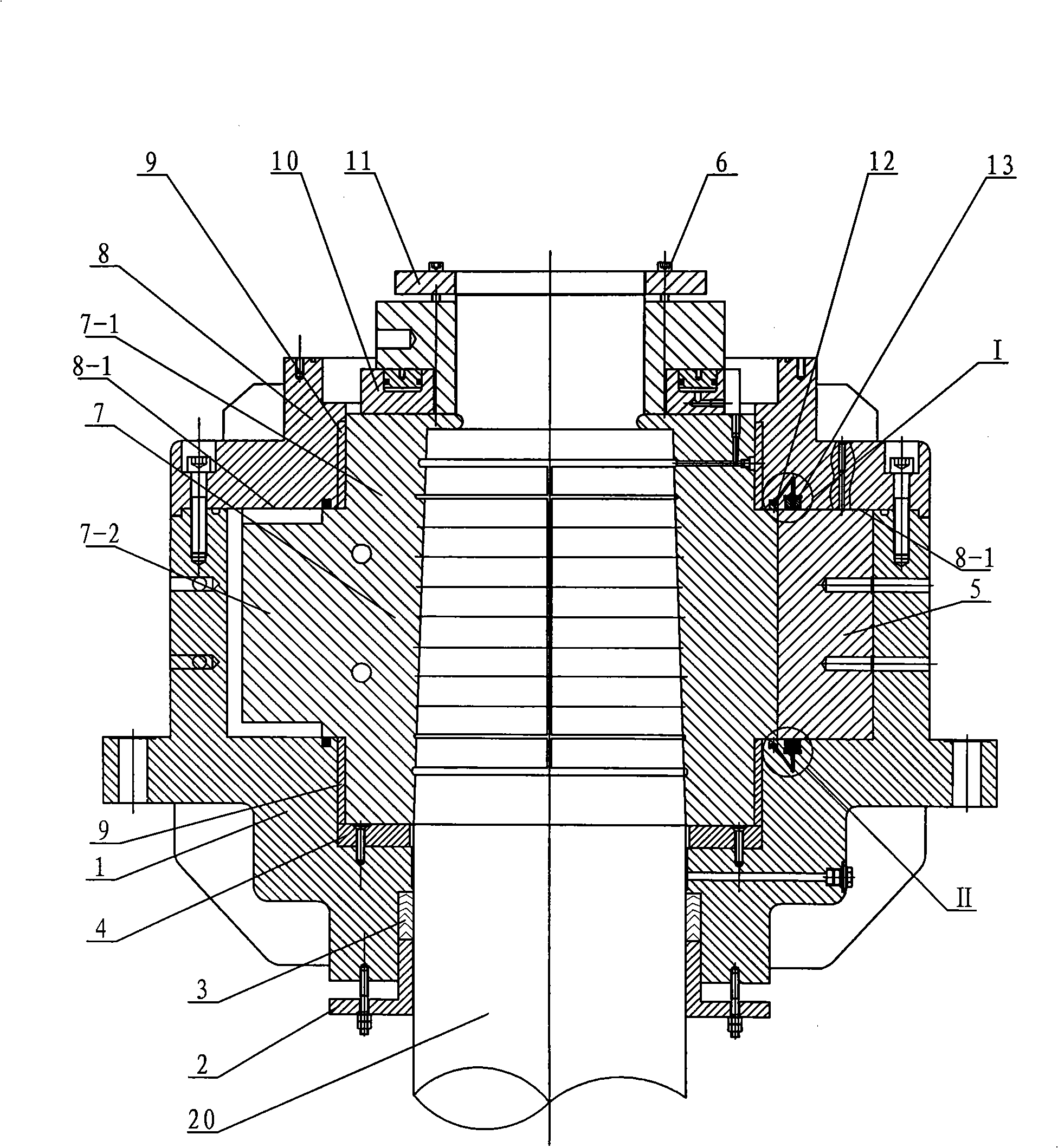
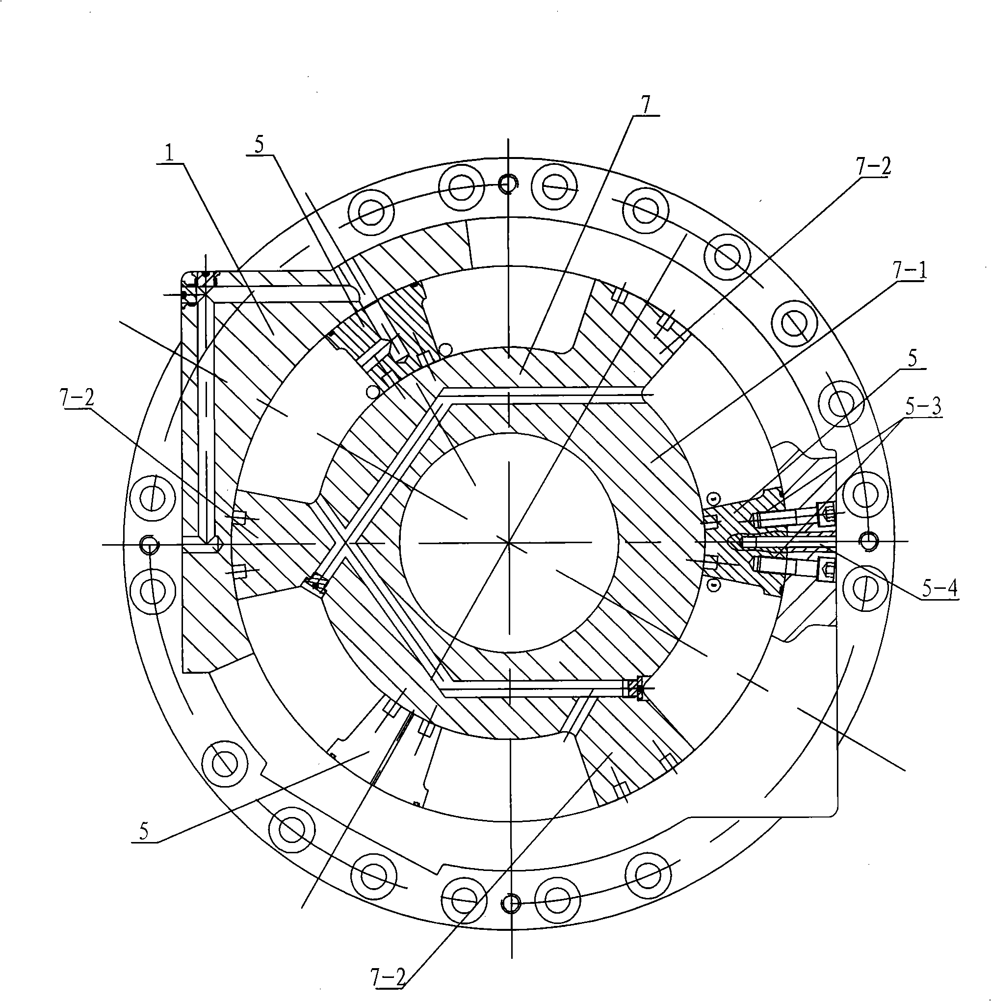
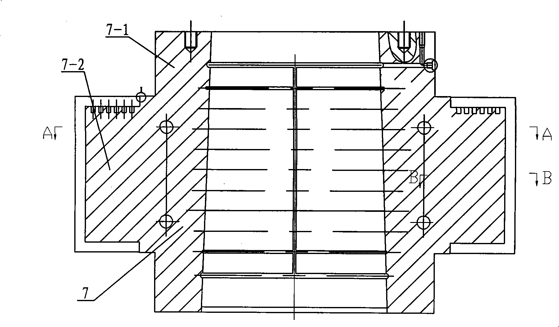
[0007] Specific implementation mode one: combine Figure 1 to Figure 7 Describe this embodiment, which includes a housing 1, a lower end cover 2, a thrust bearing 4, a stator 5, bolts 6, a rotor body 7, an upper end cover 8, two sliding bearings 9, a pressing device 10, and an anti-loosening plate 11. Four one-way valve groups 15 and four sealing strips 16. The rotor body 7 is composed of the rotor shaft 7-1 and the moving blades 7-2. The moving blades 7-2 are evenly distributed from the cross-sectional direction of the rotor shaft 7-1. On the outer ring of the rotor shaft 7-1, the moving blade 7-2 is integrated with the rotor shaft 7-1, and the two sides of the moving blade 7-2 are respectively provided with a first valve slot 7-2-1, two second A first oil passage 7-2-2 is provided between the valve grooves 7-2-1, and two first straight grooves 7-2-3 are provided on the side end surface of the moving blade 7-2 in contact with the housing 1, A first oil hole 7-2-4 is provided...

specific Embodiment approach 2

[0008] Specific implementation mode two: combination Figure 5 , Figure 7 and Figure 8 Describe this embodiment, the sealing strip 16 of this embodiment is composed of a sealing outer strip 16-1, a base 16-2 and two springs 16-3, and the sealing outer strip 16-1 corresponds to the first oil hole 7-2-4 Or one side of the second oil hole 5-5 is provided with a row of spring mounting holes 16-1-1, each spring mounting hole 16-1-1 is embedded with a base 16-2, and the spring 16-3 is arranged in the spring mounting hole 16 -1-1 and is set on the base 16-2, the sealing strip 16 has pressure equalizing grooves 16-1-2 on all three sides except the side where the spring mounting hole 16-1-1 is located, and the pressure equalizing grooves 16- 1-2 can reduce the pressure drop through the sealing strip, which is beneficial to improve the sealing effect. Sealing strip 16 cuts and forms with straight groove 5-6 on the stator 5, and base 16-2 selects No. 45 steel for use.

specific Embodiment approach 3

[0009] Specific implementation mode three: combination Figure 8 To describe this embodiment, the distance between the top end of each base 16-2 and the top end of the sealing outer strip 16-1 in this embodiment is equal. This design makes the compression amount of each spring 16-3 the same and centered, so that the sealing strip 16 can fit well with the surface of the rubbed rotor shaft 7-1.


PUM


Abstract

A low-friction high-voltage rotary vane motor based on the self-compensation composite sealing technology relates to a rotary vane motor. The rotary vane motor solves the problems of the prior rotary vane motor that: sealing between a moving vane and a stator and between the stator and a casing is realized through cast iron sealing strips, thereby resulting in poor sealing performance and small sealing pressure and restricting the application of rotary vane motor in highpower steering engine. The rotary vane motor comprises the following structure that: two one-way group valves are respectively arranged inside two first valve spools at both side faces of a moving vane; two sealing strips are respectively arranged inside two first straight grooves; a rotor body and a component of a sliding bearing are arranged on a thrust bearing inside a casing; one side of a stator is fixed on the inner side wall of the casing, while the other side is adhered to a rotor shaft; a lower end cap is arranged on the lower end face of the casing; the two one-way group valves are respectively arranged inside two valve spools on both side faces of the stator; and the two sealing strips are respectively arranged inside two second straight grooves. The low-friction high-voltage rotary vane motor adopts the one-way group valves and the sealing strips to realize radial seal, and has reliable sealing property and greater pressure, thereby enlarging the application range of rotary vane motor.

Description

technical field [0001] The invention relates to a rotary vane motor. Background technique [0002] Compared with the reciprocating steering gear, the rotary vane steering gear has the advantages of compact design, convenient installation, and small footprint. It has been widely used in many large stern-type ships and warships, and it is a promising steering gear form. For the rotary vane motor widely used on the existing rotary vane steering gear, the seal between the moving vane and the stationary vane (stator) is usually sealed by a cast iron sealing strip, such as Figure 11 As shown, the cast iron sealing strip 62 is used as the friction pair material. The cast iron sealing strip 62 is in contact with the friction surface 64 of the rotor motor, and the sealing pressure is generated by the compression spring 61 behind the cast iron sealing strip 62. This sealing form has good wear resistance, Small frictional resistance, automatic compensation after wear, long service lif...

Claims


Application Information

Patent Timeline
Patent Type & Authority Applications(China)
IPC IPC(8): F03C2/00F04C2/00F15B15/08
CPCB60G2202/22
Inventor 姜继海苏文海刘庆和
Owner HARBIN INST OF TECH
Why Eureka
Try Eureka