Position detector and display device

一种检测装置、显示装置的技术,应用在测量装置、转换传感器输出、仪器等方向,能够解决不能起到电磁屏蔽等问题

Inactive Publication Date: 2008-12-24
WACOM CO LTD
View PDF1 Cites 23 Cited by
  • Summary
  • Abstract
  • Description
  • Claims
  • Application Information

AI Technical Summary

Problems solved by technology

However, the thickness of the amorphous tape can only be manufactured to about 50 μm, so there is a problem that it cannot play the role of electromagnetic shielding

Method used


Image

  • Position detector and display device
  • Position detector and display device
  • Position detector and display device

Examples


Embodiment Construction

[0059] Use the following Figure 1 to Figure 8 An example of embodiment of the present invention will be described.

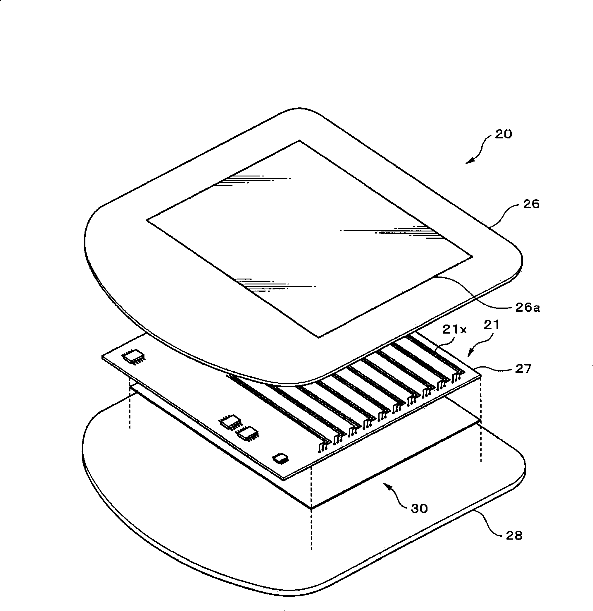
[0060] figure 1 It is an exploded perspective view of the position detection device 20 of this embodiment. As shown in the figure, a sensor substrate 27 and a magnetic circuit board 30 are disposed between the upper case 26 and the lower case 28 . Upper housing 26 has position indicator 10 (not in figure 1 shown in ) drawing screen 26a. The magnetic circuit board 30 is arranged on the surface (the lower case 28 side) opposite to the surface (the upper case 26 side) of the sensor substrate 27 facing the position indicator 10 . The sensor coil 21 for detecting the coordinates of the position indicator 10 is arranged on the sensor substrate 27 .

[0061] In the sensor coil 21, a sensor coil 21x for detecting an x-coordinate is formed on one surface of a sensor substrate 27, and a sensor coil 21y for detecting a y-coordinate is formed on the other surface. ...


PUM


Abstract

The present invention provides a position detector, comprising a light weight magnetic path plate which can realize performance of static screen and prevention of magnetic noise influence simultaneously. The magnetic path plate with an amorphous layer and non-amorphous metal layer is arranged on a surface opposite to a surface facing the position indicator. Therefore, composing a position detector which can make the magnetic path plate lightweight, and can input coordinate even an electronic circuit and the like are arranged at the background of the sensor substrate. Thereby the equipment comprising the position detector can be lightweight by using the position detector with the structure on a computer or the like.

Description

technical field [0001] The present invention relates to a position detection device for performing an input operation using, for example, a pen-shaped position indicator, and a display device using the same, and more particularly to a device for position detection by electromagnetic action. Background technique [0002] Currently, there are various types of input devices for electronic devices such as personal computers (PCs) and PDAs (Personal Digital Assistants), such as keyboards, mice, and joysticks. Among such input devices, there is a so-called pen-tablet in which coordinates are input by drawing on a dedicated plate-shaped device using a pen-shaped device. [0003] Figure 9 It is a perspective view which shows the structural example of a tablet. Figure 9 The tablet shown is composed of a pencil-shaped position indicator (pen) 10 and a sensor (tablet) 20 on which a sensor substrate 27 is arranged. The details will be described below. A coil for position detection is...

Claims


Application Information

Patent Timeline
Patent Type & Authority Applications(China)
IPC IPC(8): G06F3/033G06F3/046
CPCG01D5/2006G06F3/03545G06F3/046
Inventor 福岛正光伊藤雅充堀江利彦
Owner WACOM CO LTD
Why Eureka
Try Eureka