
Remote automatic control switch apparatus

A switch device and remote technology, which is applied to record carriers used in machines, instruments, and induction record carriers, etc., can solve the problems of no transceiver, limited working period, limited communication distance, etc.

Inactive Publication Date: 2011-06-01
上海平安投资有限公司
View PDF0 Cites 8 Cited by
  • Summary
  • Abstract
  • Description
  • Claims
  • Application Information

AI Technical Summary

Problems solved by technology

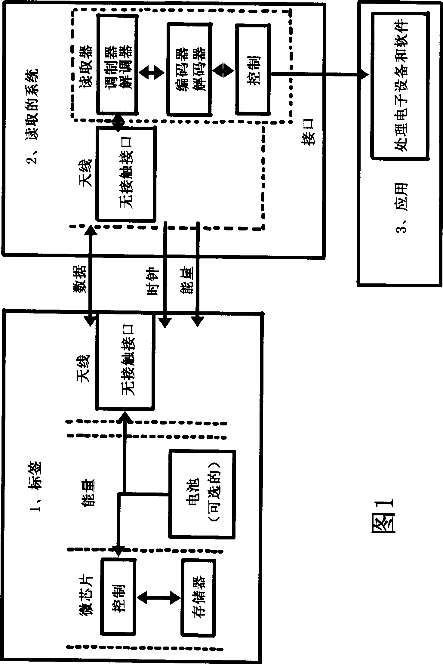
However, due to the limitation of battery capacity, the active tag also has a limitation of working period and requires regular maintenance. At the same time, it is costly and has a large volume and weight.
The semi-passive tag is powered by its own battery, but has no independent transceiver. It must use the same technology as the passive tag to communicate with the reading device. Its own power supply is mainly responsible for the maintenance of memory data and the function of additional module maintenance. Therefore , semi-passive tags do not have the problem of insufficient content capacity and single function of passive tags, and do not require frequent maintenance cycles of active tags. The cost is significantly lower than that of active tags, but the communication distance is greatly limited.

Method used


Image

  • Remote automatic control switch apparatus
  • Remote automatic control switch apparatus
  • Remote automatic control switch apparatus

Examples


Embodiment Construction

[0027] Hereinafter, the remote automatic control switching device of the present invention will be described in detail with reference to the accompanying drawings.

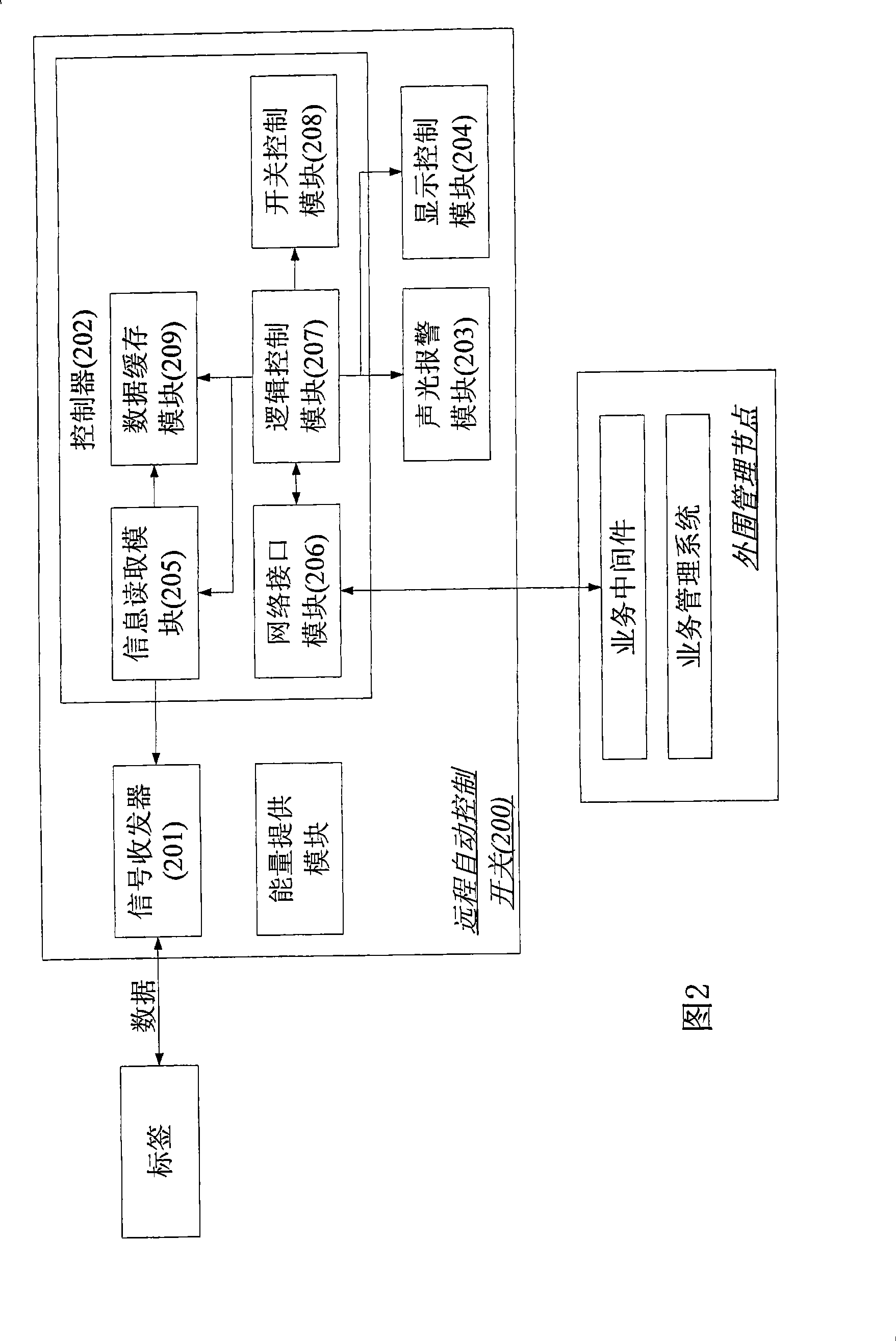
[0028] As shown in the figure, FIG. 2 shows a structural block diagram of the remote automatic control switch device according to the first embodiment of the present invention. As shown in FIG. 2 , the remote automatic control switch 200 of the present invention includes a signal transceiver 201 and a controller 202 . Wherein, the signal transceiver 201 can transmit a signal, for example, a radio wave with a certain wavelength. According to the attenuation of the radio wave in the nearby space, the radio wave can cover a certain range around the signal transceiver, and, in the During the working period of the remote automatic control switchgear, the signal transceiver continuously emits signals. Here, after the signal reaches the object to be detected, it can be fed back via the readable label of the object to be...


PUM


Abstract

The invention discloses a remote automatic controlled switching device which comprises a signal transceiver and a controller. The signal transceiver emits signals to cover a certain space around the switching device and receives the signals that are fed back by signals emitted by the signal transceiver and exist in a to-be-detected object existing in the space, or the signals emitted by the to-be-detected itself. The controller can read information carried by the signals received by the signal transceiver and control the on-off operation of the switching device according to a judging process preset in the controller and based on the information. The remote automatic controlled switching device of the invention can enhance the convenience of the user and the security of the switching device.

Description

technical field [0001] The invention relates to a remote automatic control switch device, more specifically, relates to a device for automatically controlling a switch according to information received from a remote location. Background technique [0002] In the existing switchgear, such as the common automatic door in the building, it can detect that someone needs to pass when the person is approaching, so that the door can be opened automatically, and it can be closed after a period of time, so that no manual operation is required. [0003] In addition, in the swipe card access control system commonly used in various companies, the person with the company's employee card makes his employee card close to the sensor in the access control system, which is also commonly called "swipe card", and then the sensor reads the employee The information on the card opens the door and closes it within a certain period of time. [0004] It can be seen that in the existing automatic door...

Claims


Application Information

Patent Timeline
Patent Type & Authority Patents(China)
IPC IPC(8): G07C9/00G06K7/00G06K19/00
Inventor 黄林祺白凌姿卢纯青俞哲黄平
Owner 上海平安投资有限公司
Learn More