
Battery module

A technology of battery modules and unit cells, which is applied in the direction of batteries, battery pack components, circuits, etc., can solve the problems that it is difficult to prevent the position of the unit cells from changing, it is difficult to keep the installation position unchanged, and the uneven deformation of the battery module is achieved. Shorten working hours, prevent irregular changes in performance, and improve productivity

Inactive Publication Date: 2008-12-24
SAMSUNG SDI CO LTD
View PDF1 Cites 12 Cited by
  • Summary
  • Abstract
  • Description
  • Claims
  • Application Information

AI Technical Summary

Problems solved by technology

[0006] In view of the fact that a battery module is composed of several or more than a dozen unit cells connected to each other, because a conventional battery module requires a cooling structure, a safety mechanism, a system circuit, etc. that can easily dissipate the heat generated in each unit cell, this The problem with the battery module is that the overall volume increases
If the size of the battery module is increased, there is a problem that not only the weight of the battery module increases, but also the design of equipment (especially vehicles) assembled with the battery module becomes complicated
[0012] However, such a conventional battery module has a problem that, when an external force is applied, uneven deformation may occur in the battery module, which will reduce the reliability of the battery module, making it difficult to adjust the installation position of the partition wall (between the partition walls). spacing) remain the same, and it is difficult to prevent the position of the unit cells from changing

Method used


Image

  • Battery module
  • Battery module
  • Battery module

Examples


Embodiment Construction

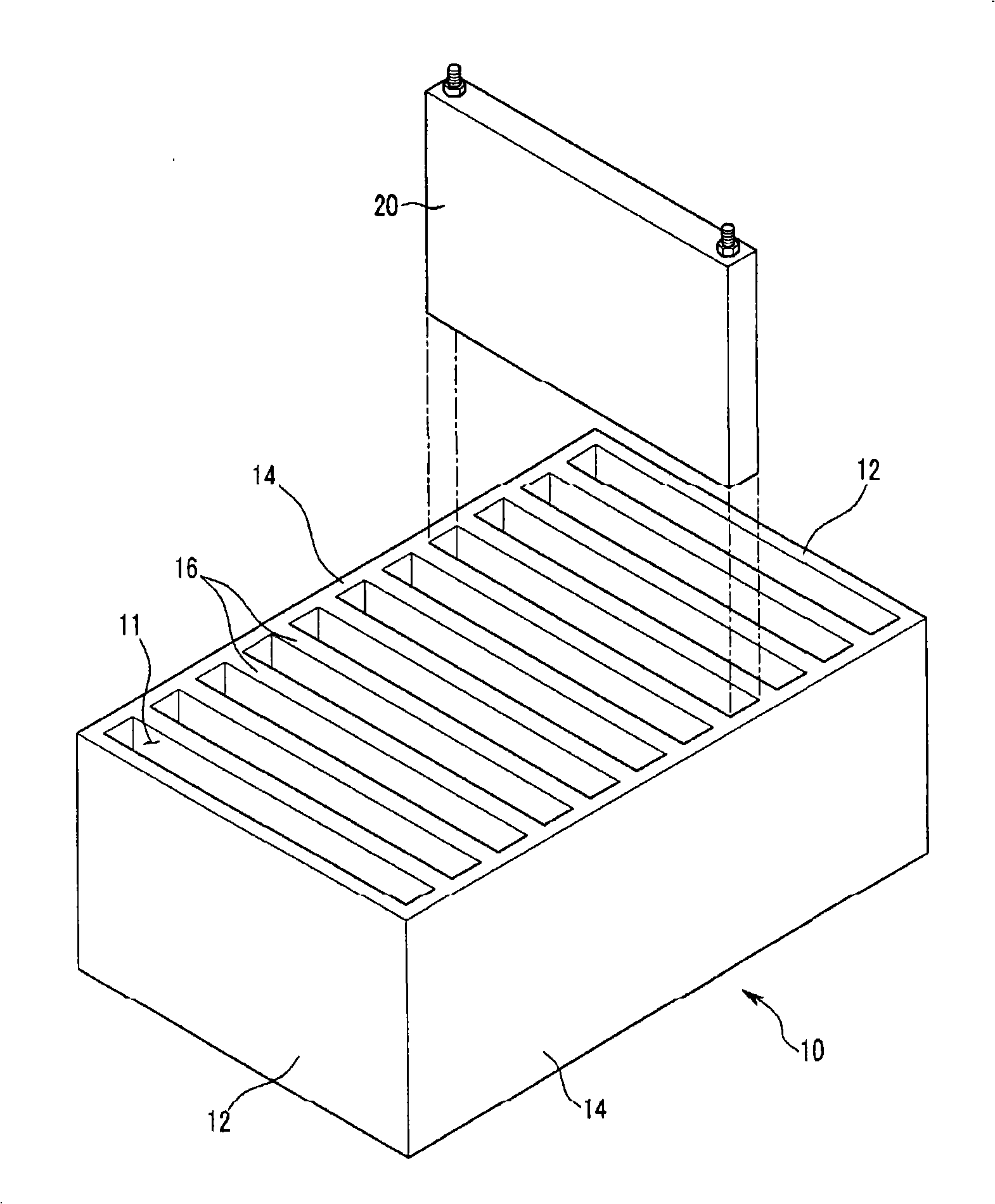
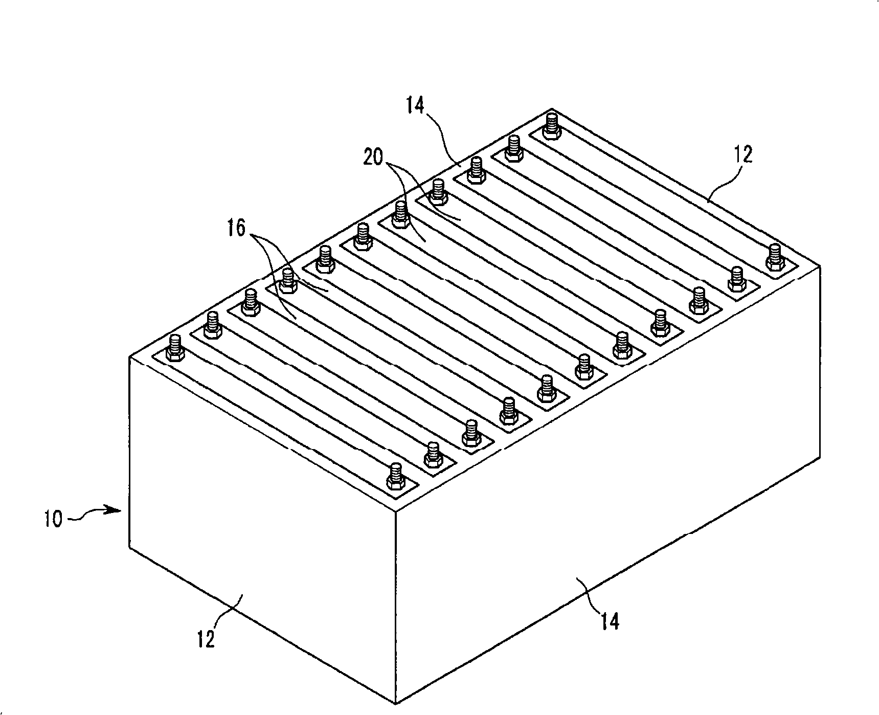
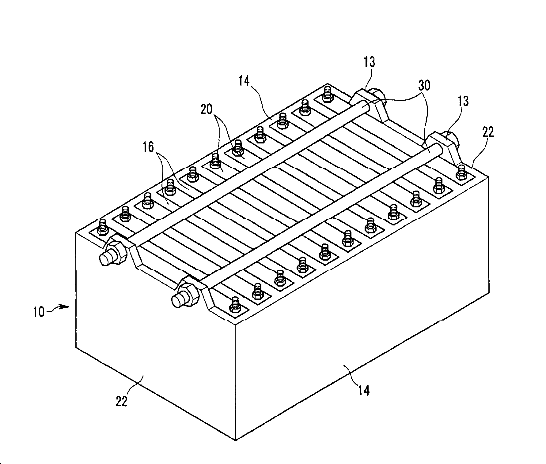
[0049] now refer to figure 1 and 2 , the battery module of the present embodiment includes a box-shaped case 10 with at least one side open, a plurality of partition walls 16 integrally formed in the case 10 at certain intervals, and a plurality of partition walls 16 separated from each other by the partition walls 16 and inserted thereinto. A unit cell 20 in the casing 10 .

[0050] As described above, since the plurality of partition walls 16 are installed in the case 10 at intervals, spaces 11 are formed between the partition walls 16 to insert the unit cells 20 therein.

[0051] The housing 10 has a pair of support plates 12 formed to face each other at both ends of the housing and a pair of side plates 14 connected to the support plates 12 at both ends thereof and to two sides of each partition wall 16. The edges are fixed together. The support plate 12 of the housing 10 is installed parallel to the partition wall 16 , while the side plate 14 is installed vertically to...


PUM


Abstract

A battery module includes a case with at least one face which is opened, a plurality of partition walls fixedly installed at predetermined intervals in the case, and a plurality of unit batteries which are separated from each other with the partition walls therebetween to be inserted into the case. The battery module may include a battery fixing structure which is installed between the case and the unit batteries to fix the unit batteries so as to prevent positional movement of the unit batteries in the case. The battery fixing structure may be a concavo-convex engaging structure including fixing projections and projection receiving portions.

Description

[0001] This application is a divisional application of the invention patent application with the application number 200510129182.3, the application date is October 28, 2005, the applicant is Samsung SDI Co., Ltd., and the invention name is "battery module". technical field [0002] The present invention relates to a battery module, in particular to a battery module capable of accommodating a partition wall at a fixed installation position and improving the bonding force of unit cells in a housing. Background technique [0003] In general, secondary batteries are rechargeable and can be used repeatedly. In particular, secondary batteries including only one battery cell are mainly used in various small portable electronic devices, such as for cellular phones, laptop computers, cameras, and camcorders. A high-capacity secondary battery (hereinafter referred to as a 'battery module') is composed of a plurality of single cells {hereinafter referred to as 'unit batteries' (unit ba...

Claims


Application Information

Patent Timeline
Patent Type & Authority Applications(China)
IPC IPC(8): H01M2/10H01M2/02
CPCY02E60/10H01M2220/20
Inventor 全伦哲李建求金泰容
Owner SAMSUNG SDI CO LTD
Learn More