Camera module

A technology of camera module and conductive layer, which is applied in the direction of TV, color TV parts, electrical components, etc., can solve the problems of destroying input/output radio waves, adverse effects of radio sensitivity, etc., and achieve the effect of blocking EMI

Inactive Publication Date: 2008-12-24
LG INNOTEK CO LTD
View PDF0 Cites 11 Cited by
  • Summary
  • Abstract
  • Description
  • Claims
  • Application Information

AI Technical Summary

Problems solved by technology

[0003] In the case of a portable terminal equipped with a camera module, electromagnetic interference, radio frequ

Method used


Image

  • Camera module
  • Camera module
  • Camera module

Examples


Embodiment Construction

[0033] Hereinafter, the embodiments will be described with reference to the drawings.

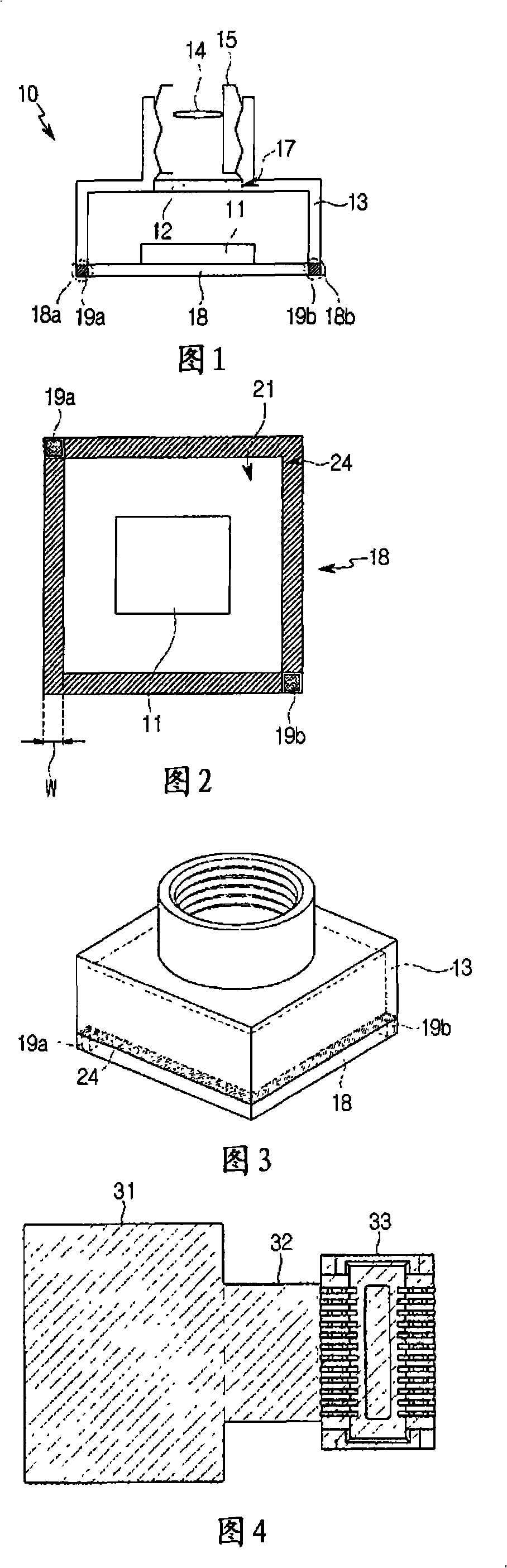
[0034] FIG. 1 is a cross-sectional view illustrating a camera module according to an embodiment.

[0035] The camera module 10 according to the embodiment includes an image sensor 11 , a holder 13 , a lens barrel 15 and a printed circuit board 18 . The holder 13 is arranged on a printed circuit board 18 . An opening portion 17 is formed in the holder 13 to expose the image sensor 11 . An IR filter 12 may be provided in the opening portion 17 to block external infrared rays. In addition, a connector may be connected to the printed circuit board 18 to transmit the light signal generated by the image sensor 11 to the main board.

[0036] A lens barrel 15 is fixed to an inner side wall of the holder 13 to fix the lens 14 . As shown in FIG. 1 , the lens barrel 15 may be formed in a thread structure or a linear structure.

[0037] According to an embodiment, a conductive layer may be formed ...


PUM


Abstract

A camera module is provided with a lens part including a lens and a lens barrel, a holder coupled with the lens part and formed with a first conductive layer, and a printed circuit board electrically connected to the first conductive layer while supporting the holder.

Description

technical field [0001] Embodiments of the present invention relate to a camera module. Background technique [0002] With the advancement of communication technology and digital information processing technology, portable terminals having various functions such as information processing and manipulation, communication, and image information input / output have been developed. Such a portable terminal is equipped with a camera module to obtain images. [0003] In a case where a portable terminal is equipped with a camera module, electromagnetic interference, radio frequency (RF) noise, and thermal noise damage input / output radio waves and exert adverse effects on radio sensitivity. Contents of the invention [0004] Embodiments of the present invention provide a camera module capable of effectively blocking EMI, RF noise, and thermal noise. [0005] According to an embodiment, a camera module includes: a lens part including a lens and a lens barrel; a holder coupled with th...

Claims


Application Information

Patent Timeline
IPC IPC(8): H04N5/225
CPCH05K9/0064
Inventor 金珉秀
Owner LG INNOTEK CO LTD
Why Eureka
Try Eureka