Spinal crest elastic internal fixation device

An internal fixator and fixator technology, applied in the direction of internal fixator, fixator, internal bone synthesis, etc., can solve the problems of spinous process fracture, insufficient fixation force of implant, spinous process cutting, etc.

Inactive Publication Date: 2011-05-04
SOUTHERN MEDICAL UNIVERSITY
View PDF6 Cites 0 Cited by
  • Summary
  • Abstract
  • Description
  • Claims
  • Application Information

AI Technical Summary

Problems solved by technology

However, because the bone strength of the spinous process itself is weak, and all the forces are concentrated on the spinous process, it is prone to fracture and cutting of the spinous process
In order to avoid the above problems, the method of not fixing with bolts is often used clinically, but there are contradictions that the implant is not strong enough to fix and the implant is easy to loosen
Although the developer of the above-mentioned implant has set some small protrusions on the outer side of the U-shaped elastic sheet main body and designed the inner sides of the U-cards on both sides as a serration to its product, it is attempted to increase the Increase the bonding force between it and the spinous process to avoid loosening of the implant, but practice has proved that the above shortcomings cannot be overcome

Method used


Image

  • Spinal crest elastic internal fixation device
  • Spinal crest elastic internal fixation device
  • Spinal crest elastic internal fixation device

Examples


Embodiment Construction

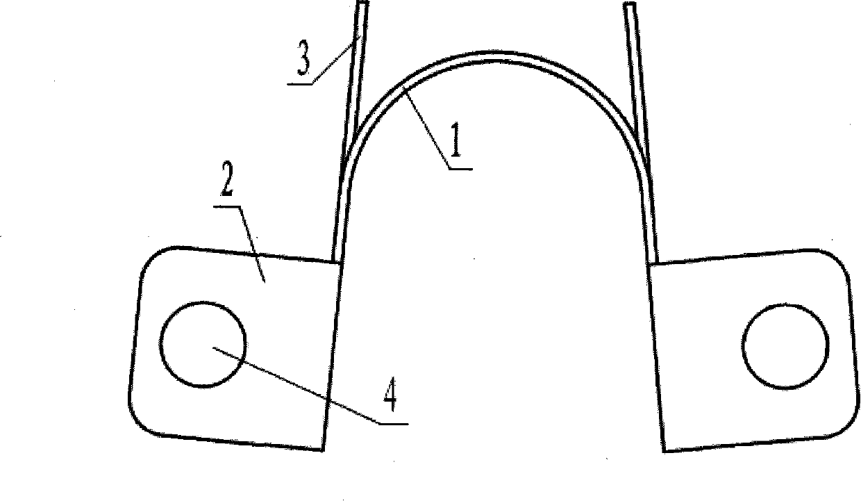
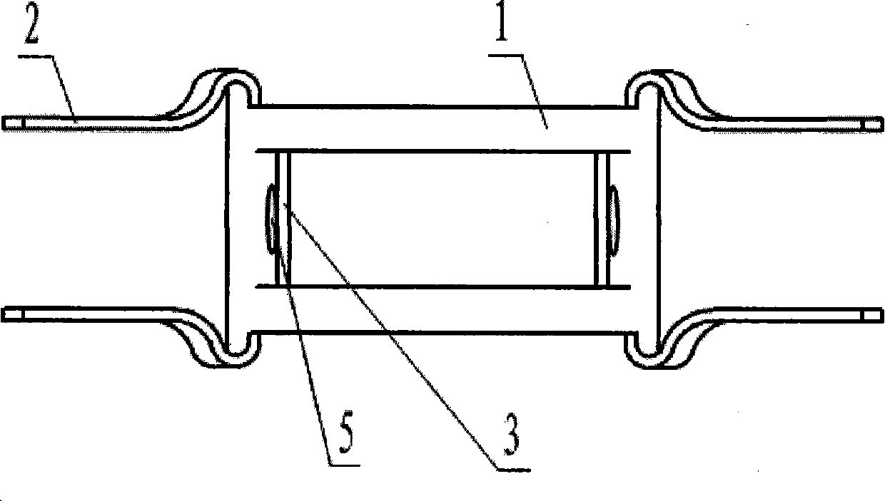
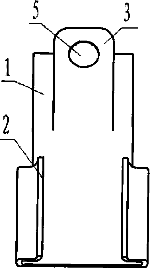
[0017] see Figures 1 to 3 , the U-shaped elastic sheet 1 and the two U-shaped cards 2 and the wings 3 on both sides are composed of Figure 4 Shown is stamped from sheet of titanium alloy. see Figure 4 , the elastic sheet 1 is formed by bending the part A in the figure, the two U-shaped cards 2 are formed by folding the B parts at both ends relative to each other, and the two side wings 3 are formed by hollowing out the C part and then turning up relatively. In order to avoid the spinous process fracture caused by external force directly acting on the spinous process, the root connected with the U-shaped clip 2 and the U-shaped elastic sheet 1 is bent into an outwardly arched arc (see figure 2 and image 3 ). see Figures 1 to 3 and combine Figure 4 , The bolt holes 4 on the two U-shaped cards 2 and the self-tapping screw holes 5 on the two wings 3 can be punched together when punching, or can be processed separately after punching.

[0018] according to Figures 1 to...


PUM


Abstract

The invention discloses an inner elastic fixer of vertebral spinous process. The fixer comprises a U-shaped elastic strip (1) and a U-shaped clip (2) arranged at both sides of the U-shaped elastic strip. The invention is characterized in that lateral wings (3) are arranged at both sides of the bottom of the U-shaped elastic strip (1) respectively, the lateral wings (3) extend along the negative direction of a U-shaped opening and a tapping screw hole (5) is arranged on each lateral wing (3). The invention fastens a fixed bolt on the upper spinous process and the lower spinous process by the U-shaped clip and adopts the tapping screw hole to fix the lateral wing on a vertebral lamina at the root of the spinous process, thus greatly reducing force acting on the spinous process so as to improve the stability of fixing and effectively prevent the fracture and incision of the spinous process.

Description

technical field [0001] The invention relates to a spinal elastic internal fixer, which is suitable for treating lumbar spinal canal stenosis and instability. Background technique [0002] In traditional spinal diseases, spinal degeneration is a common cause besides injuries caused by traumatic fractures. Spinal segmental instability caused by lumbar spine degeneration leads to abnormal local stress and spinal canal stenosis. This abnormal stress distribution and spinal canal stenosis are considered to be one of the pain mechanisms of low back pain. Lumbar spinal stenosis and lumbar instability often go together, because lumbar instability accelerates the narrowing of the lumbar spinal canal, and posterior lumbar decompression surgery often damages the structure of the posterior lumbar spine and aggravates lumbar instability. At present, the main surgical methods for the treatment of the above-mentioned diseases are posterior decompression of the spinal canal, bone graft fus...

Claims


Application Information

Patent Timeline
Patent Type & Authority Patents(China)
IPC IPC(8): A61B17/70
Inventor 靳安民陈远明
Owner SOUTHERN MEDICAL UNIVERSITY
Why Eureka
Try Eureka