Spin anchoring pipe

A technology of anchor grouting and anchor pipe, which is applied in the installation of anchor bolts, mining equipment, earthwork drilling and mining, etc. It can solve the problems of unsatisfactory roadway surrounding rock control, difficulty in roadway surrounding rock control and maintenance, poor stability of roadway surrounding rock, etc. Problems, to achieve the effect of adjustable curing time, improve the effect of axial and radial constraints, and improve the reliability of anchoring

Pending Publication Date: 2019-03-26
陕西蒲白矿山支护有限公司
View PDF0 Cites 0 Cited by
  • Summary
  • Abstract
  • Description
  • Claims
  • Application Information

AI Technical Summary

Problems solved by technology

[0002] In recent years, with the increasing scale of mining, the mining depth has increased year by year, the mining depth of coal mines has increased at a rate of 8-12m / year, and the eastern mines are developing at a rate of 10-25m / year. The pressure is also increasing, especially the deep roadway is located in the unstable rock mass affected by mining, weak rock formation and broken zone, and the weak surface of the surrounding rock is developed, which makes the stability of the surrounding rock of the roadway poor. great difficulty
Under these complex and difficult conditions, the use of conventional anchors / cables or sheds for support cannot meet the requirements for roadway surrounding rock control, resulting in serious roadway deformation and damage and high maintenance costs

Method used


Image

  • Spin anchoring pipe

Examples


Embodiment 1

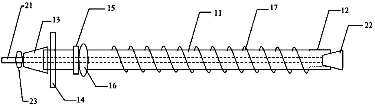
[0034] The spin anchor injection pipe is characterized in that it includes an anchor pipe body and an internal injection tensioning set; the anchor pipe body includes a steel pipe 11, and one end of the steel pipe 11 is provided with a longitudinal crack 12, and the other end is provided with a reducing sleeve 13, A tray 14, a retaining ring 15, a rubber stopper 16 and an anchor screw 17 are sequentially arranged between the reducing sleeve 13 and the longitudinal crack 12, and the retaining ring 15 is welded on the steel pipe 11 and the distance between the reducing sleeve 13200~ 400mm, the rubber stopper 16 is close to the retaining ring 15, the anchor screw 17 is welded on the steel pipe 11 body; One end of the internal injection tensioning pipe 21 close to the longitudinal crack 12 is welded with a vertebral body 22 , and the other end is provided with a primary anchor nut 23 outside the reducing sleeve 13 .

Embodiment 2

[0036] The spin anchor injection pipe is characterized in that it includes an anchor pipe body and an internal injection tensioning set; the anchor pipe body includes a steel pipe 11, and two longitudinal cracks 12 are evenly arranged at one end of the steel pipe 11, and a variable diameter sleeve is provided at the other end 13. A tray 14, a retaining ring 15, a rubber stopper 16 and an anchor screw 17 are sequentially arranged between the reducing sleeve 13 and the longitudinal crack 12. The retaining ring 15 is welded on the steel pipe 11 and the distance between the reducing sleeve 13200mm, the rubber stopper 16 is close to the retaining ring 15, the anchor screw 17 is welded on the steel pipe 11; Pipe 21 , the inner injection tension pipe 21 is welded with a vertebral body 22 at one end close to the longitudinal crack 12 , and the other end is provided with a primary anchor nut 23 outside the reducing sleeve 13 .

Embodiment 3

[0038] The spin anchor injection pipe is characterized in that it includes an anchor pipe body and an internal injection tensioning set; the anchor pipe body includes a steel pipe 11, and three longitudinal cracks 12 are evenly arranged at one end of the steel pipe 11, and a variable diameter sleeve is provided at the other end 13. A tray 14, a retaining ring 15, a rubber stopper 16 and an anchor screw 17 are sequentially arranged between the reducing sleeve 13 and the longitudinal crack 12. The retaining ring 15 is welded on the steel pipe 11 and the distance between the reducing sleeve 13300mm, the rubber stopper 16 is close to the retaining ring 15, the anchor screw 17 is welded on the steel pipe 11; Pipe 21 , the inner injection tension pipe 21 is welded with a vertebral body 22 at one end close to the longitudinal crack 12 , and the other end is provided with a primary anchor nut 23 outside the reducing sleeve 13 . The outer diameter of the retaining ring 15 is φ40.


PUM


Abstract

The invention relates to a spin anchoring pipe comprises an anchor pipe body and an inner injection tensioning sleeve. The anchor pipe body includes a steel pipe, one end of the steel pipe is providedwith a longitudinal crack, and the other end is provided with a variable diameter sleeve head. A tray, a check ring, a rubber slurry-stopping plug and an anchoring spinning wire are sequentially arranged between the variable diameter sleeve head and the longitudinal crack, the check ring is welded to the steel pipe and has a distance of 200-400 mm from the variable diameter sleeve head, the rubber slurry-stopping plug is close to the check ring, the anchoring spinning wire is welded to a pipe body of the steel pipe, the inner injection tensioning sleeve includes an inner injection tensioningpipe passing through the steel pipe, a cone body is welded to one end of the inner injection tensioning pipe close to the longitudinal crack, and the other end is provided with an initial anchoring nut on the outer side of the variable diameter sleeve head. The spin anchoring pipe performs high-pressure grouting and can improve the diffusion radius, the anchor pipe supporting performance is improved, the grouting is reliable, and the construction is convenient.

Description

technical field [0001] The invention relates to a spin anchor injection tube. Background technique [0002] In recent years, with the increasing scale of mining, the mining depth has increased year by year, the mining depth of coal mines has increased at a rate of 8-12m / year, and the eastern mines are developing at a rate of 10-25m / year. The pressure is also increasing, especially the deep roadway is located in the unstable rock mass affected by mining, weak rock formation and broken zone, and the weak surface of the surrounding rock is developed, which makes the stability of the surrounding rock of the roadway poor. Great difficulty came. Under these complex and difficult conditions, the use of conventional anchor rods / cables or sheds for support cannot meet the requirements for roadway surrounding rock control, the roadway is seriously deformed and damaged, and the maintenance cost is high. [0003] High-strength anchor-grouting support technology is a new roadway suppor...

Claims


Application Information

Patent Timeline
Patent Type & Authority Applications(China)
IPC IPC(8): E21D21/00E21D20/02
CPCE21D21/0013E21D20/003E21D20/02E21D21/0026E21D21/008
Inventor 张立强
Owner 陕西蒲白矿山支护有限公司
Why Eureka
Try Eureka