Flying shear machine upper and lower knife rack gear drive device

A technology of gear transmission mechanism and flying shear machine, which is applied in the direction of gear transmission device, transmission device, belt/chain/gear, etc., which can solve the problems of meshing gear misalignment and impact, and achieve the elimination of meshing gap, elimination of clearance, and overcoming transmission error Effect

Inactive Publication Date: 2008-12-31
JIANGSU YAWEI MACHINE TOOL
View PDF1 Cites 1 Cited by
  • Summary
  • Abstract
  • Description
  • Claims
  • Application Information

AI Technical Summary

Problems solved by technology

However, it cannot bear the misalignment and impact problems between meshing gears caused by large load pulsation shocks

Method used


Image

  • Flying shear machine upper and lower knife rack gear drive device
  • Flying shear machine upper and lower knife rack gear drive device

Examples


Embodiment Construction

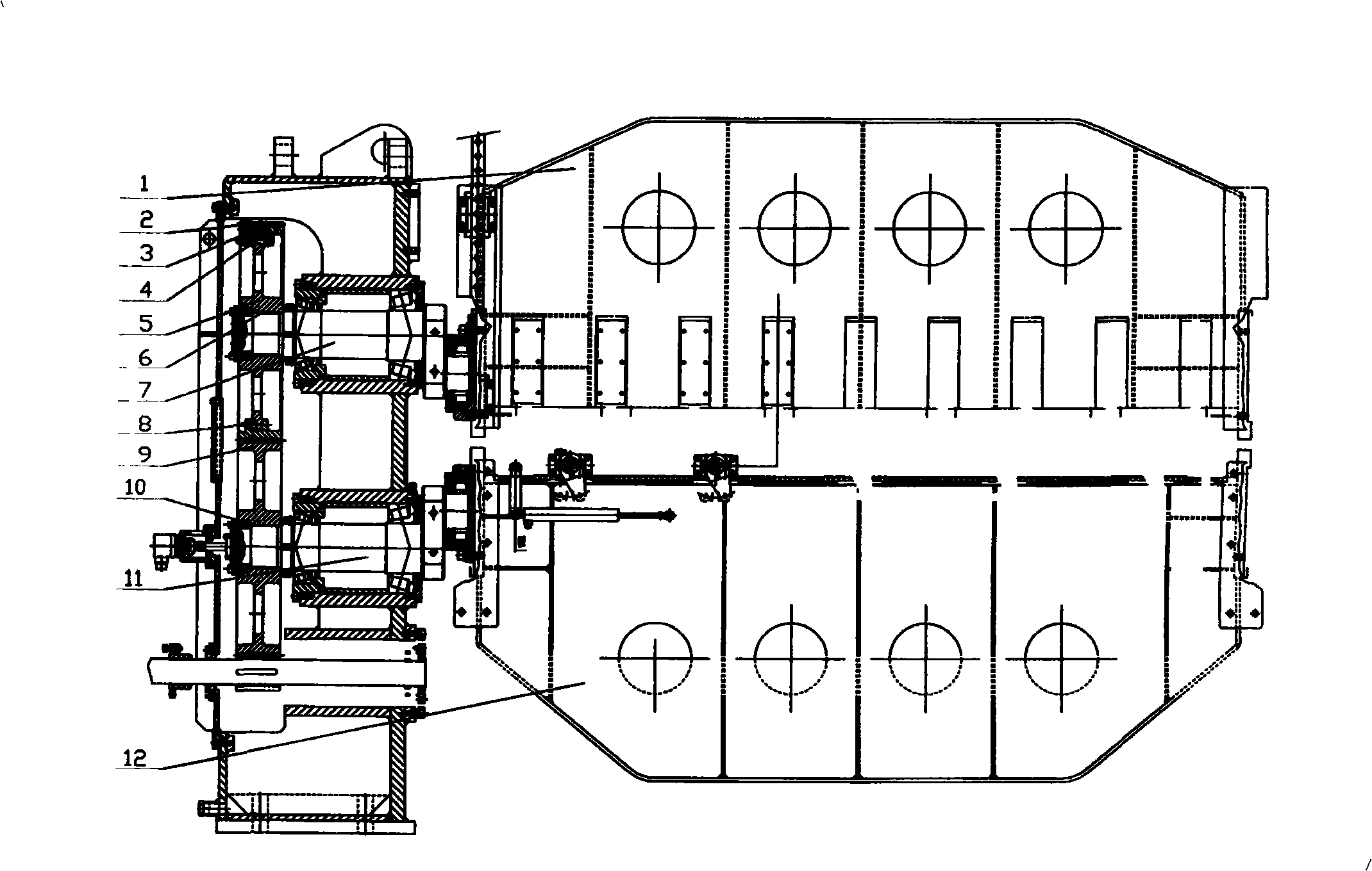
[0020] Such as figure 1 , the present invention includes the main transmission gear, the lower tool rest transmission gear 9 and the upper tool rest transmission gear which are arranged on the main transmission shaft, the upper tool rest eccentric shaft 7 and the lower tool rest eccentric shaft 11, and the upper tool rest transmission Gear is made of wheel core 5, main gear 2, pinion gear 3, eccentric adjustment shaft 8 and bolt 4, and wheel core 5 is connected with upper knife rest eccentric shaft 7.

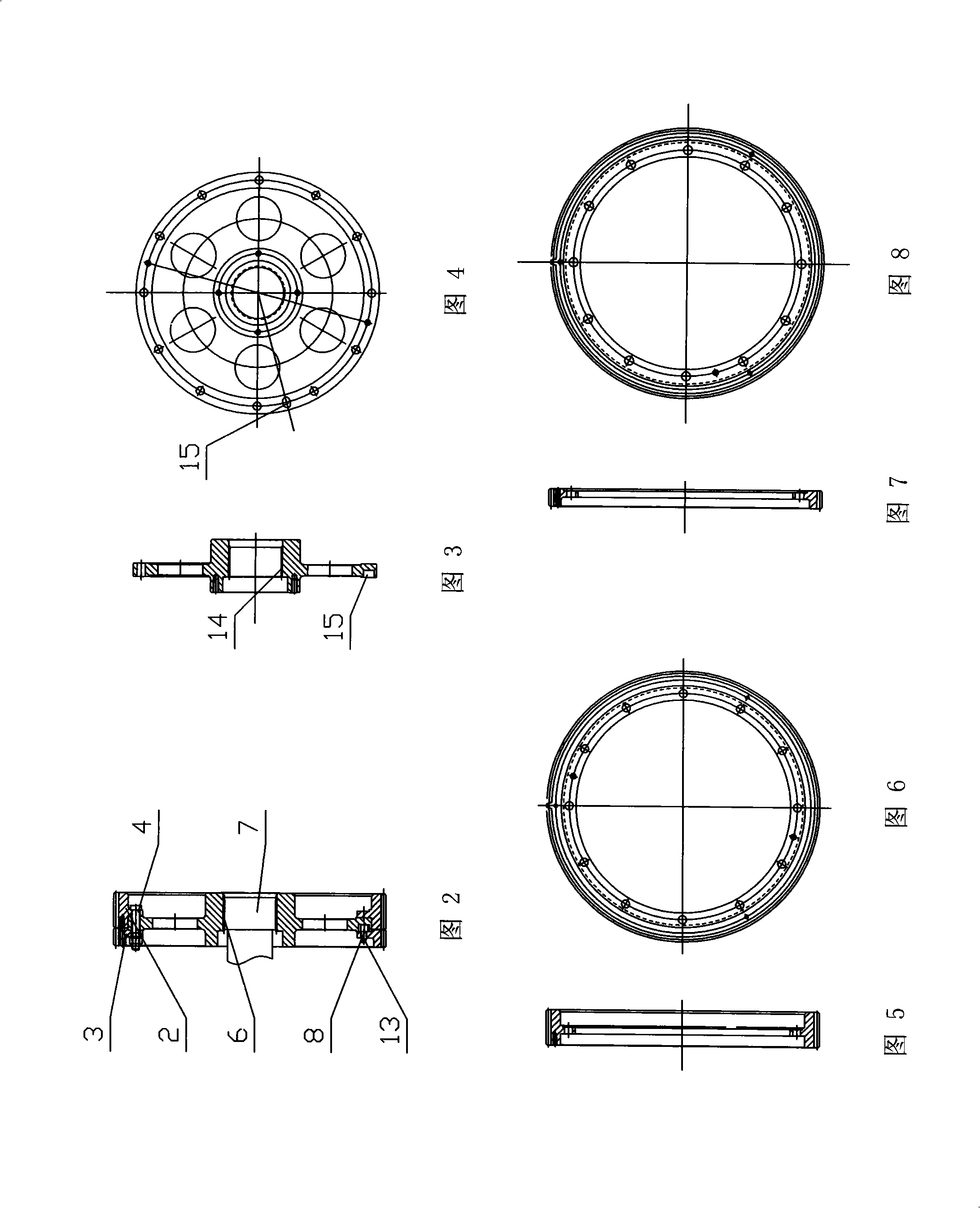
[0021] As shown in Figures 2 to 8, the main gear 2 and the pinion gear 3 are sequentially arranged on the outer ring of the wheel core 5 from the inside to the outside; an eccentric adjustment shaft 8 is set between the pinion gear 3 and the wheel core 5; the wheel core 5, the main gear 2, A number of connecting holes are respectively arranged on the same circumference of the auxiliary gear 3, and the apertures of the connecting holes on the auxiliary gear 3 are slightly larger...


PUM


Abstract

The invention relates to a gear driving mechanism for the upper cutter frame and the lower cutter frame of the flying shear, in particular to a gear driving mechanism with variable working conditions. The gear driving mechanism comprises a main drive gear, a lower cutter frame drive gear and an upper cutter frame drive gear which are mutually meshed and arranged on a main drive shaft and eccentric shafts of the upper and the lower cutter frames, wherein, the upper cutter frame drive gear is composed of a gear core, a master gear, a pinion, an eccentric regulating shaft and bolts, wherein the gear core is connected with the eccentric shaft of the upper cutter frame, and the master gear and the pinion are arranged on the outer circle of the gear core in series; the eccentric regulating shaft is arranged between the pinion and the gear core; a plurality of connecting holes are respectively arranged on the identical circumference of the gear core, the master gear and the pinion, and the bore diameters of the connecting holes on the pinion are slightly larger than that of the connecting holes on the master gear and the gear core; the gear core, the master gear and the pinion are connected through the bolts penetrating through each connecting hole. The gear driving mechanism has the advantages that the clearances between the meshed gears are effectively eliminated, the driving error is overcome, and the impaction between the gears generated due to the clearances is eliminated as well.

Description

technical field [0001] The invention relates to a gear transmission mechanism with variable working conditions, in particular to a transmission mechanism for eliminating the transmission error and inter-gear impact vibration caused by the gap between transmission gears caused by the alternating force of a flying shear. Background technique [0002] The trajectory of the upper and lower tool holders of the double crankshaft flying shear is to maintain relative circular motion on the same vertical plane. According to the nature of the action, it can be divided into board chasing motion and return motion, and the shearing of the board is completed between the two actions. When cutting the sheet, a reverse force is generated between the upper and lower knives. Because the transmission gears of the upper and lower tool holders are meshed with each other, there is a gap between the transmission gears between the upper and lower tool holders. The reverse force will cause collision...

Claims


Application Information

Patent Timeline
Patent Type & Authority Applications(China)
IPC IPC(8): F16H1/20F16H55/18
Inventor 王金荣蔡诚蒋国美居春红张冠军吉素琴
Owner JIANGSU YAWEI MACHINE TOOL
Why Eureka
Try Eureka