[0026] As established from my patent works of 6,277,041 and the conjoining 6,524,201, and relative to the encompassing papers foundation created in 1994 that have both associational and developmental characteristics by a single hand author, this is a kit dart having “mix-and-match” capabilities across both soft tip and steel tip venues; but, within the aspect of said kit against the commonality of diameters and materials, in general, an appropriate
facet hereof is the capability of being cross-applicational to known prior art because of the known aspect of utilizing the proven polybag approach for display of the various components at the retail level, called grid development hereby through the usage of “X & Y” axes against said retail board value, thereby allowing market driven values to produce a program necessary for the evolution of this encompassing kit darts approach to utility. Thus, it is known within the envelope hereof that certain portions for this approach to uncommon utility, through the factual difference of a rubber spring eliminating fatigue found in the “
metal” spring utilization, that my scoring member and matching endcap can be employed in darts barrels already on the marketplace because of that impact controlling cylinder, the latter expanding oblately by lateral expression to disperse negative forces that can cause rejection and / or deflection known in prior art, thereby furthering the marketing grid employed herewith.
[0028] What this invention does is modify the available shafts forwardly or aftwardly against the placement into an appropriate
barrel for the completed dart; with any prior art shaft without a collar requiring a female
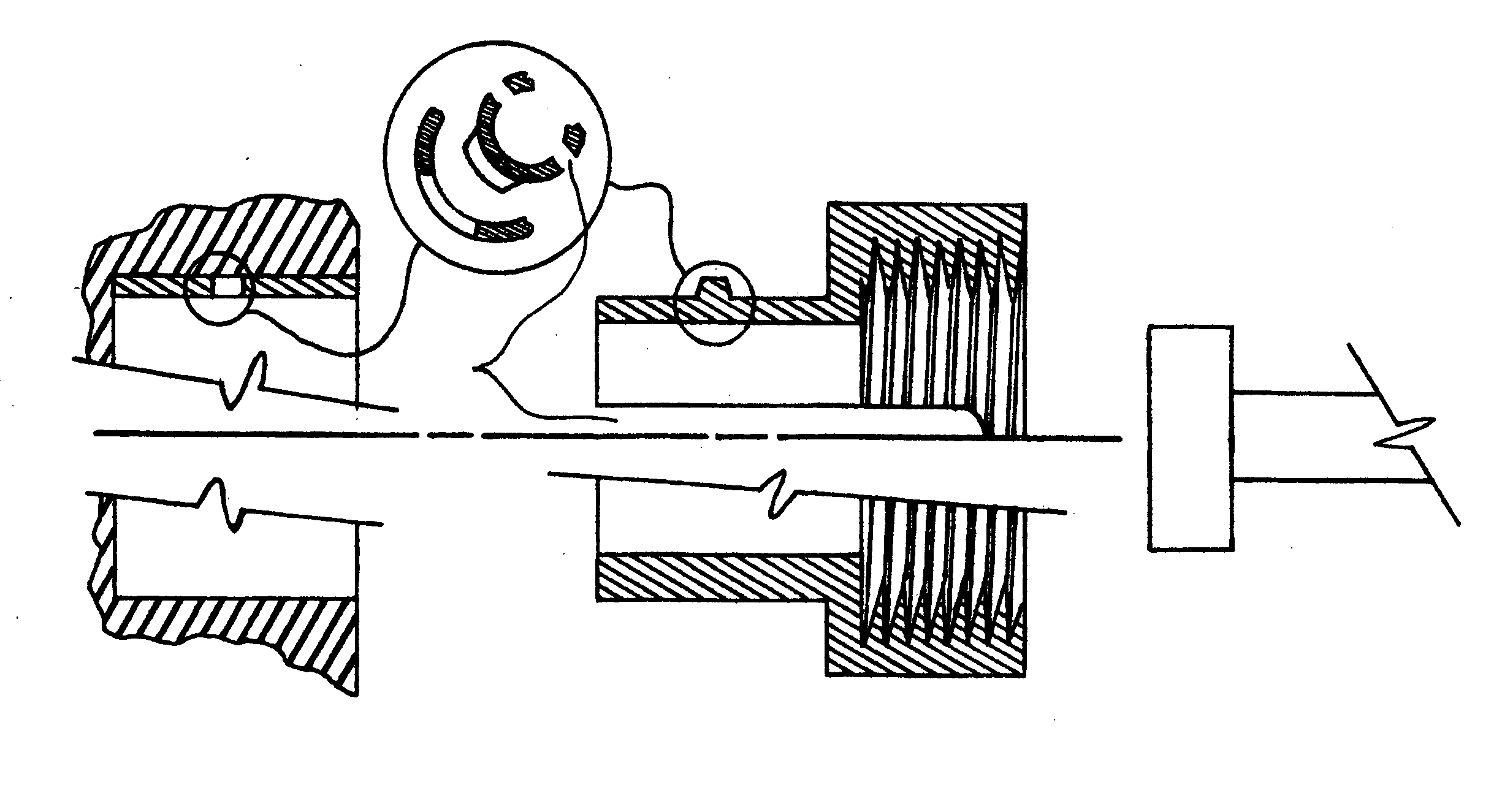
receiver for click snap location of the enlarged collar, and inwardly of that is the noted flat being received in said collared end to prevent rotation, with that inwardly collar reciprocally having a flat slidably matching a positional reference within the endcap and axially referenced to further eliminate rotation against
hand manipulation and / or impact considerations. But, in the matching of said collar to the endcap's internal structure, it is entirely possible to shorten the axial dimension from the forward end of the shaft's opening that interacts with the shaft's chord oriented collar portion, thereby allowing firstly the non-rotational aspect to be coupled to the rotational aspect through axially oriented travel of said collar past a determined point within that endcap, with a taper at that transition allowing an at rest return when resetting of the actional parts prior to the next competitive use by the player.
[0031] And, in the use of a grip managing portion or separated body as shown in my grant of 6,524,201, it is possible to employ the obverse variant shown here, it being a radial series of ribs extending past the primary
barrel diameter along it's axis, they being separated incrementally so as to improve finger / grip capture. While it is possible that their outward projection may become damaged through repeated trajectory impacts, even though their radial measurement increase against the chosen
diameter is just thousandths of an inch, it's the ability to replace just one portion of the completed darts body that allows this simple convergence towards utility.
[0032] Within the replaceable aspects of this work, it is possible to use a variation of the loc-tite thread bearer that joins segments together for a completed darts body. Whether forward or aftward, against possible wear experienced by the abrasion caused from axial movement of the working portions, a tight fitting sleeve is loc-tite positioned between complex endward embodiments requiring extremely high tolerance
machining and pre-formed tubes of sintered
tungsten that only require the finish
machining at both the external values and the staged bores to complete the
assembly. The internal cuts of the end pieces conform to the insertable component values expressed hereby, while the proposed tube that may complete a portion whether used fore or aft of the grip provisioner continues the use of the noted thread bearer to connect same. Thus, it is possible to replace any one of the shown segments by the simple prior art act of heating at the joinery to break the loc-tite bond prior to parts replacement for the completed portional
assembly.
[0033] A further development is the modified usage of the works found in 1994, which eliminates the need to utilize loc-tite in stress related areas that might be conducive to failure, by the change of the annotated
circlip of Nov. 21, 1994 to a loc-tite sleeve with two portional slots located 180 degrees apart and circumferentially oriented; they relating to male prongs depending radially outwardly from a slide-in collar of close fitting means to said
fixed position, this thread carrying body having two spring slots 180 degrees apart and placed 90 degrees
out of phase from the noted partial slot
receiver and partial prongs relating thereto. The simple values of and for engagement of the male and female portions, against the displacement of the noted slots that allow
radial displacement during
insertion into the
receiver sleeve therefor, is created by
insertion of the enlarged shaft depending axially inwardly that is found on either the flights shaft or scoring shaft that slidably relates to the threaded barrel endcap of this invention, with rotational closure of that endcap establishing stability in this close fitting approach. Removal of same, if desired, is through the use of a reverse jaw pliers mechanism and requiring nothing more than a simple axial pull due to the taper found on the male prongs, as this would reacquaint the found spring slot into the noted
insertion value for displacement of the
diameter. With this addition, caused by the sometimes found need to wait for a period longer than is equitable in the game venue due to the need for the general use of loc-tite to substantially cure, the requirement of any kind of heat value is also negated through this simple approach, thereby establishing the necessary cross-relational aspect for both steel tip and soft tip darts that this invention addresses.
[0034] Against the duplex
annotation noted for weight inserts, found in 6,277,041 and 6,524,201, further possibilities involve a cylindrical
tungsten billet having a fixed shaft extending from one or both ends; with the length and amalgam properties from 50 / 50 / to 95 / 5 creating the weighting feature that allows
personalization from that KIT DART aspect. The outward end / s of that locating shaft comprising either a concave face or partial bore, with either approach being utilized to provide a locus for at least one end of the rubber spring member of this invention, said resilient body expanding laterally during moments of impact to provide axial stability for those impinging darts members during that positioned stress.

