

Accuracy self-adapting continuous complicated wave form synthesis method
A synthesis method and waveform synthesis technology, applied to controllers with pulse train output signals, electric controllers, etc., can solve the problems of waveform amplitude, cycle, phase cannot be flexibly controlled, waveform distortion, etc., to improve control accuracy and efficiency, the effect of convenient vibration control
- Summary
- Abstract
- Description
- Claims
- Application Information
AI Technical Summary
Problems solved by technology
Method used
Image

Examples
Embodiment Construction
[0015] The present invention will be further described below in conjunction with the accompanying drawings and embodiments.
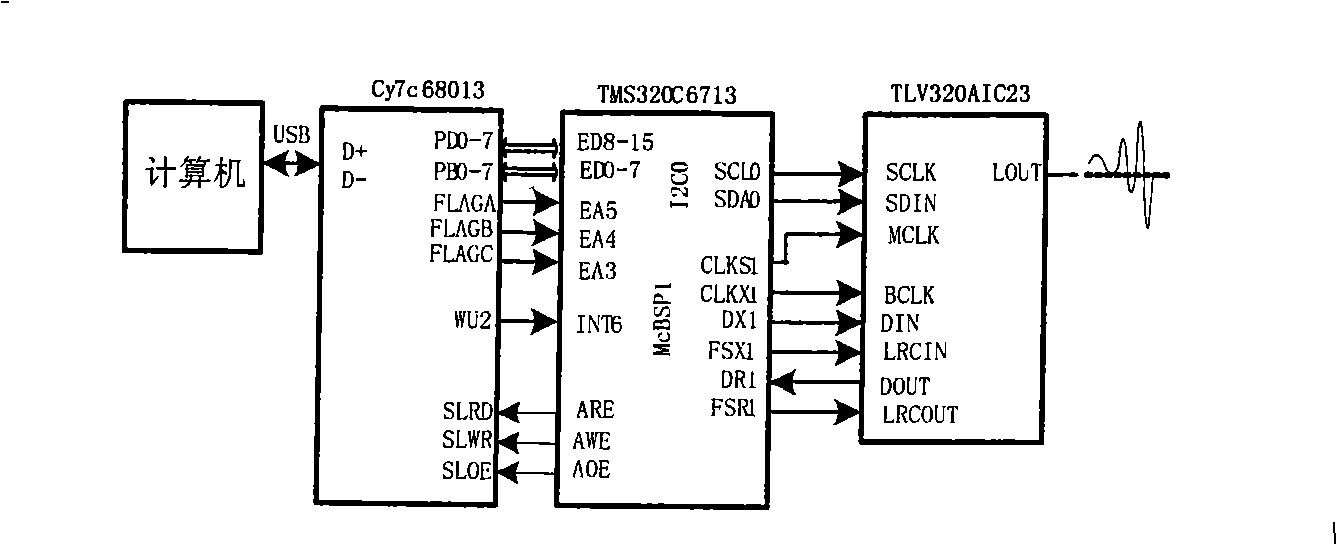
[0016] The equipment of this synthesis method comprises computer, general serial interface chip Cy7c68013, DSP chip TMS320C6713 and based on Sigma-Delta decoding chip TLV320AIC23, computer is connected DSP by its USB interface and general serial interface chip Cy7c68013, and DSP is through general serial buffer interface McBSP Connect the decoder chip TLV320AIC23.
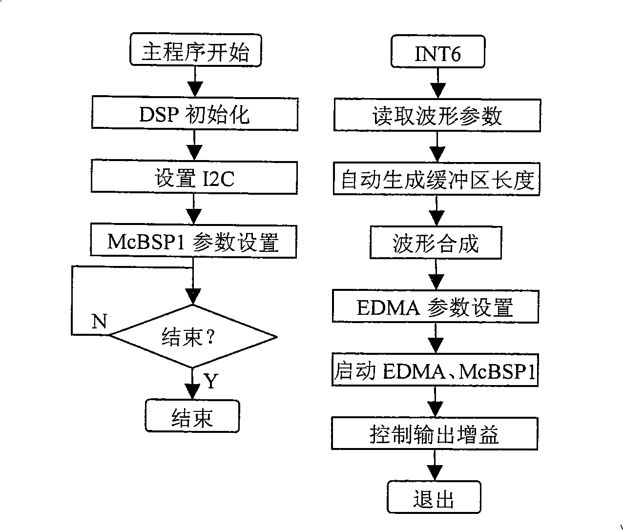
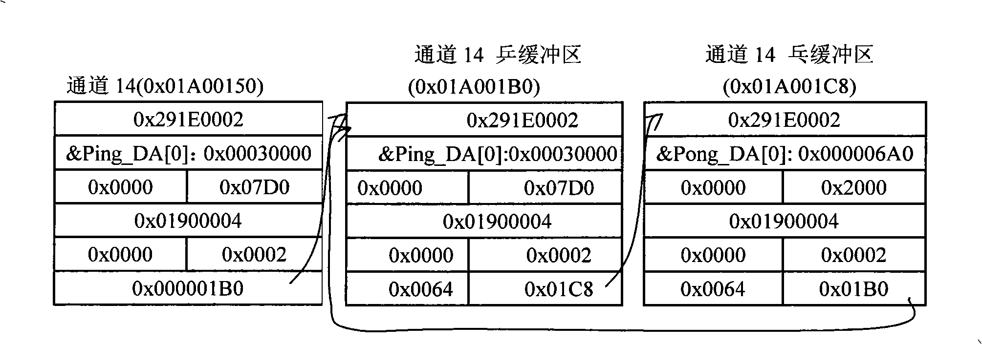
[0017] The synthesis method is as follows: the control command of the host is sent to Cy7c68013, Cy7c68013 triggers the DSP to generate an interrupt, the DSP receives the corresponding control command, starts the program that has been loaded into the DSP, the program generates the waveform type and its related parameters according to the needs of the host, through the automatic The adaptive method calculates the length of the buffer, generates the corresponding discrete waveform and puts it ...
PUM
 Abstract
Description
Claims
Application Information