Concrete vibrating robot

A robot and concrete technology, applied in the field of intelligent robots, can solve problems such as inability to vibrate, narrow space, and reduce the service life of concrete, and achieve the effects of high vibration compactness, accelerated construction progress, and high vibration efficiency

Inactive Publication Date: 2018-11-13
HOHAI UNIV
View PDF6 Cites 8 Cited by
  • Summary
  • Abstract
  • Description
  • Claims
  • Application Information

AI Technical Summary

Problems solved by technology

At present, the domestic concrete vibrating process is in a relatively backward state, only reaching the level of foreign developed countries 40 years ago, and there are three main deficiencies: ①The vibrating quality standard is low, and the detection means are backward
The vibrating quality standard set by domestic concrete products is low, the concrete vibrating quality inspection standard is not strict, and the corresponding inspection methods are lacking, resulting in low quality concrete products; ②The construction environment is harsh and the vibrating process is complicated
In some projects, the reinforcement mesh and formwork on the site of concrete vibration are densely distributed, the space is narrow, and it is difficult for construction personnel to enter, resulting in the quality of vibration not being guaranteed or vibrating, which reduces the service life of concrete
③Concrete vibrating specification requirements are complicated. Taking the plug-in concrete vibrating rod as an example, the specification requires straight up and down, fast insertion and slow extraction, etc., uniform insertion points, moderate speed, etc. Factors put forward very high requirements, and the quality and efficiency of concrete vibration are often difficult to guarantee, which delays the progress of the project

Method used


Image

  • Concrete vibrating robot
  • Concrete vibrating robot
  • Concrete vibrating robot

Examples


Embodiment Construction

[0021] The present invention is described in further detail now in conjunction with accompanying drawing. These drawings are all simplified schematic diagrams, which only illustrate the basic structure of the present invention in a schematic manner, so they only show the configurations related to the present invention.

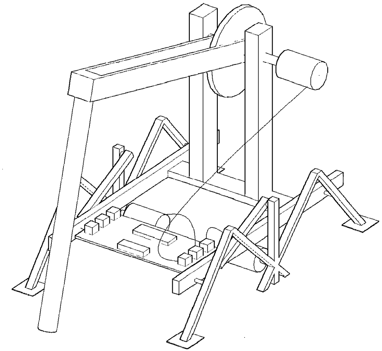
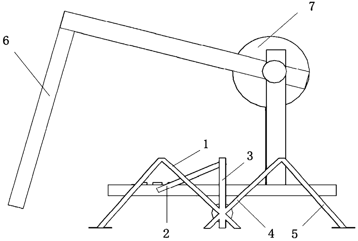
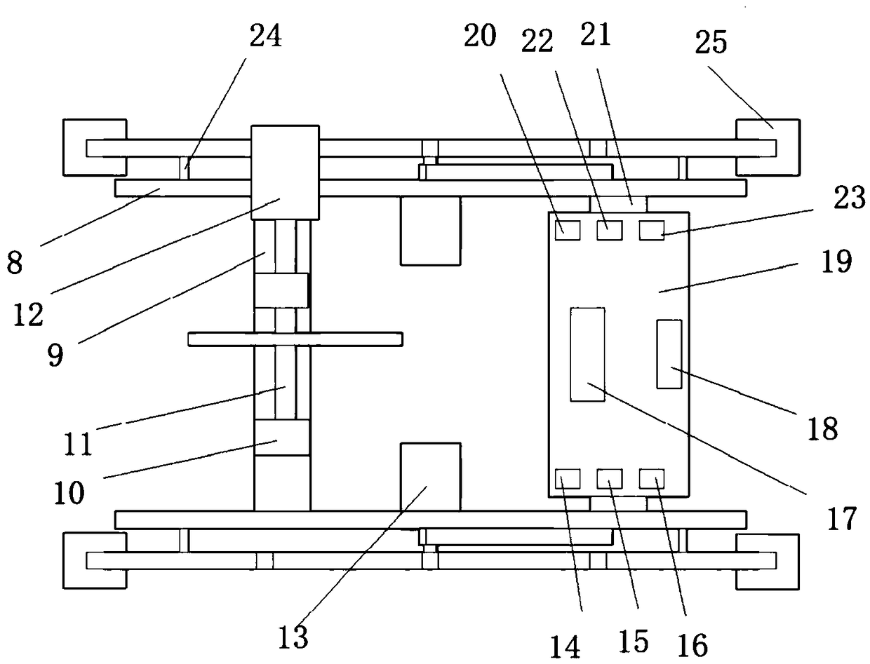
[0022] Such as Figure 1-3 As shown, a concrete vibrating robot includes a hexapod mobile chassis, a control assembly, a driving module, and a vibrating module.

[0023] The hexapod mobile chassis consists of a base plate and mechanical legs (referring to mechanical front legs and mechanical rear legs, connecting legs, and fixed legs). The four corners of the floor are supported by flat soles 25 . The bottom plate is composed of two 192mm double-hole beams (bottom plate rear beam 9, bottom plate front beam 21) and two 220mm single-hole beams (bottom plate longitudinal beam 8, the two bottom plate longitudinal beams 8 are arranged parallel to each other), in ...


PUM


Abstract

The invention relates to a concrete vibrating robot which can be used for vibrating of concrete at a construction site. The concrete vibrating robot is mainly composed of the following parts of (1) asix-legged mobile chassis, (2) a control assembly, (3) a driving module and (4) a vibrating module. According to the concrete vibrating robot, a vibrating bar is fixed to the multi-leg robot, the travelling direction and speed of the vibrating robot can be wirelessly controlled remotely through an APP, opening and the vibrating frequency of the vibrating bar can be further wirelessly controlled remotely, and thus precise vibrating is achieved; the concrete vibrating robot is small in size and can adapt to narrow and complex terrains; the vibrating compactness is high, the vibrating quality isgood, the vibrating efficiency is high, the time and labor are saved, and all-weather vibrating can be achieved; the construction period is shortened, operation is convenient, mastering is quick, andthe requirement for works is low; travelling and vibrating of the vibrating robot can be conveniently controlled through the mobile phone APP, and the requirements for the physical strength and experience of constructors are much lower than the requirements of hand-held vibrating for the physical strength and experience of the constructors; and through mounting and vibrating simulation, the feasibility and reliability of concrete vibrating of the concrete vibrating robot are proved.

Description

technical field [0001] The invention relates to a robot model, in particular to an intelligent robot which belongs to the field of engineering construction and can be used for vibrating concrete. Background technique [0002] During engineering construction, the performance of concrete is affected by many factors such as materials, environment, construction and standards. From the point of view of the influence of construction on the performance of concrete, the concrete vibration process is undoubtedly the most important factor. The compactness of concrete vibration directly affects the strength, impermeability and frost resistance of concrete, and has a great impact on the construction quality and use of construction projects. At present, the domestic concrete vibrating process is in a relatively backward state, only reaching the level of foreign developed countries 40 years ago. There are three main deficiencies: ①The vibrating quality standard is low, and the detection ...

Claims


Application Information

Patent Timeline
Patent Type & Authority Applications(China)
IPC IPC(8): E04G21/08
CPCE04G21/08
Inventor 强晟张智沛
Owner HOHAI UNIV
Why Eureka
Try Eureka