
Safe switching apparatus and switching method for system on chip

A system-on-chip and safety switch technology, applied in electronic switches, electrical components, pulse technology, etc., can solve problems such as inconvenient interface, accidental shutdown, and damage to the hard disk file system, so as to simplify the circuit design structure, avoid accidental startup problems, The effect of solving application bottlenecks

Active Publication Date: 2010-06-23
北京神州龙芯集成电路设计有限公司
View PDF4 Cites 0 Cited by
  • Summary
  • Abstract
  • Description
  • Claims
  • Application Information

AI Technical Summary

Problems solved by technology

The disadvantage of this switch-on technology is that even if the system is running the program, as long as the shutdown button is pressed, the system will also turn off the power supply if the important data has not been saved in time, which will cause data loss; especially for hard disk storage. For embedded systems, multiple direct key presses or wrong shutdowns will even destroy the file system of the hard disk, resulting in the embedded system being unable to read the data on the hard disk after power-on.
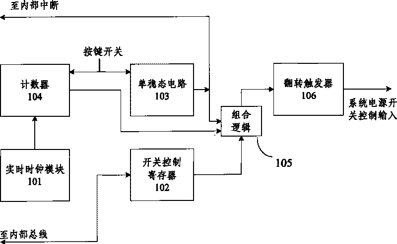
but, figure 1 The switching circuit shown is too complex to be implemented separately in a low-cost embedded system
For most embedded SoCs, it is inconvenient and costly to connect the existing switch circuit to the SoC

Method used


Image

  • Safe switching apparatus and switching method for system on chip
  • Safe switching apparatus and switching method for system on chip
  • Safe switching apparatus and switching method for system on chip

Examples


Embodiment Construction

[0034] The present invention will be described in further detail below through specific embodiments and accompanying drawings.

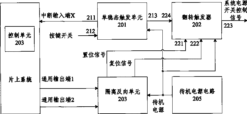
[0035] figure 2 It is a structural schematic diagram of the safety switching device of the present invention. see figure 2 , the safety switching device mainly includes: a monostable trigger unit 201, a flip trigger 202, an isolation and reverse unit 203, and a control unit 204 arranged in the system on chip, of course, also includes a standby power supply 205 for the The power supply of the safety switch machine device. Since the standby power supply is not the main component of the present invention, the monostable trigger unit 201 , flip-flop 202 , isolation and inversion unit 203 , and control unit 204 are mainly described in this specification.

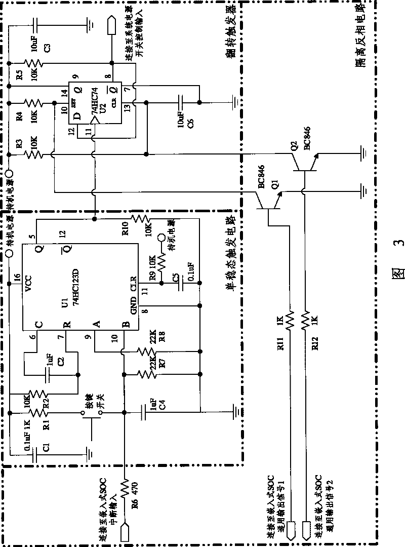
[0036] image 3 It is a circuit diagram of a specific embodiment of the safety switching device of the present invention. see below figure 2 with image 3 Come to describe the present inventio...


PUM


Abstract

The invention discloses a system-on-a-chip safe power-on and power-off device which comprises a monostable trigger unit, a T-flip-flop, an isolation reverse unit, a control unit and a standby power; wherein, the monostable trigger unit is provided with buttons and two output terminals, the first output terminal is connected with an interrupt input terminal of the system-on-a-chip, the second output terminal is connected with a clock terminal of the T-flip-flop; a setting signal terminal and a resetting signal terminal of the T-flip-flop are respectively connected with two common output terminals of the system-on-a-chip, and the output terminals are connected with a control terminal of the power of the system-on-a-chip ; the control unit is arranged in the system-on-a-chip. The invention also discloses a safe power-on and power-off method of the system-on-a-chip. The invention can set the setting signal and the resetting signal of the T-flip-flop by the movements of the buttons to control the power-on and the power-off of the power of the system-on-a-chip. By utilizing the invention, the safe power-on and power-off on the system-on-a-chip can be realized with relatively low cost.

Description

technical field [0001] The invention relates to a power supply control technology of electronic equipment, in particular to a system on chip (SOC, System on Chip) safety switching device and a safety switching method. Background technique [0002] With the rapid development of embedded system technology, SoC technology has also been applied to various fields. The so-called system-on-chip is a chip customized according to the requirements of different customers. It integrates the key components of the system into a chip to complete specific application functions. [0003] At present, many embedded system-on-chip (SOC) chips do not have a safety switch control device inside. At present, the commonly used switch technology on embedded SOC is: use an on / off button on the outside of the chip to control the flip trigger to directly open or turn off the power. The disadvantage of this switch-on technology is that even if the system is running the program, as long as the shutdown ...

Claims


Application Information

Patent Timeline
Patent Type & Authority Patents(China)
IPC IPC(8): H03K17/22
Inventor 陈学玉
Owner 北京神州龙芯集成电路设计有限公司
Learn More