
Screw nut, method of production thereof and corresponding tool

一种螺母、工具的技术,应用在金属材料制成的螺母领域,能够解决加工复杂性等问题

Active Publication Date: 2008-12-31
哈特马特.弗莱格
View PDF3 Cites 11 Cited by
  • Summary
  • Abstract
  • Description
  • Claims
  • Application Information

AI Technical Summary

Problems solved by technology

[0005] Such nuts and other known nuts have serious disadvantages in their function, especially in view of the complexity of their machining, since part of the thread or wall of the nut has to be removed by machining in order to achieve the elastic locking effect of the threaded part

Method used


Image

  • Screw nut, method of production thereof and corresponding tool
  • Screw nut, method of production thereof and corresponding tool
  • Screw nut, method of production thereof and corresponding tool

Examples


Embodiment Construction

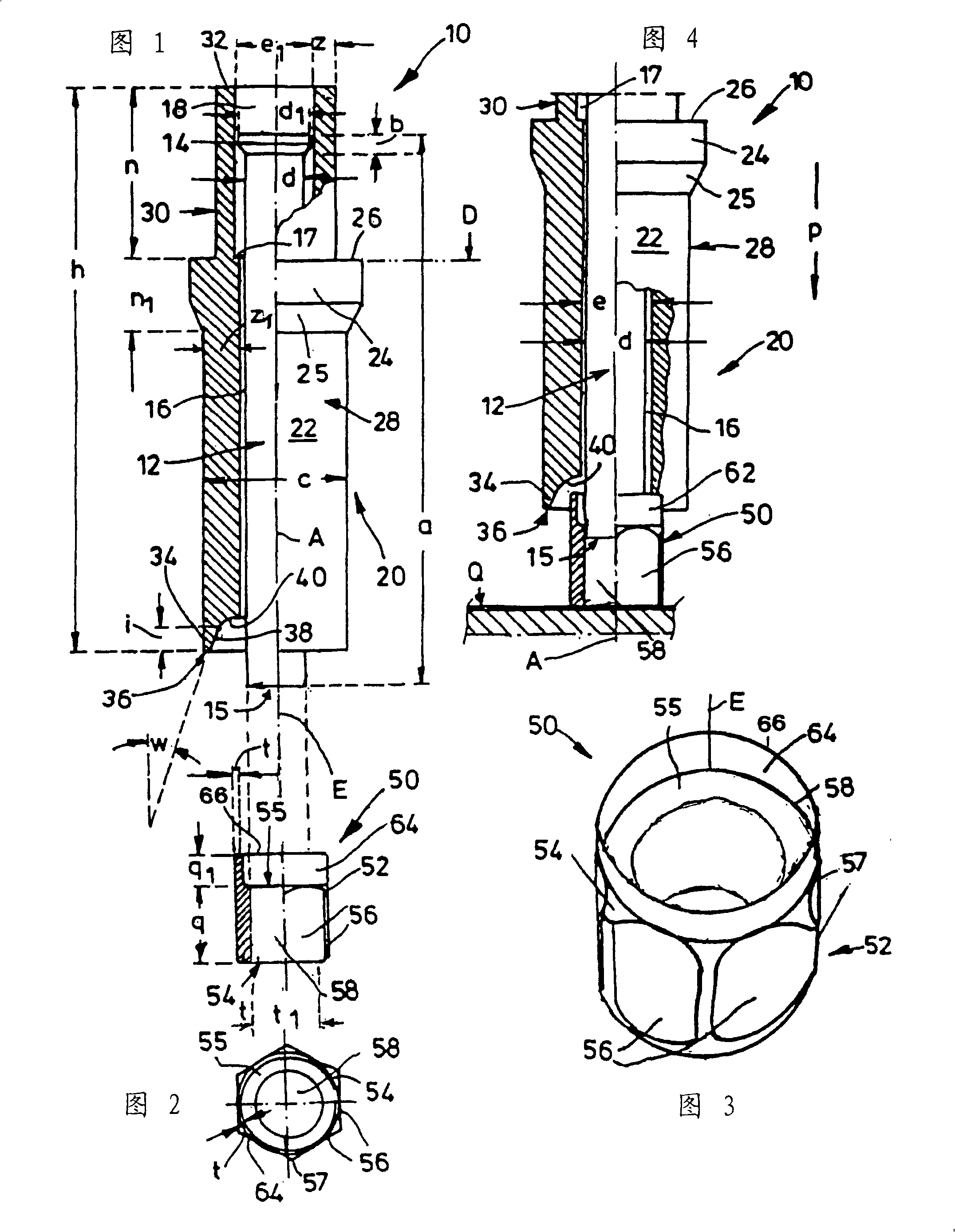
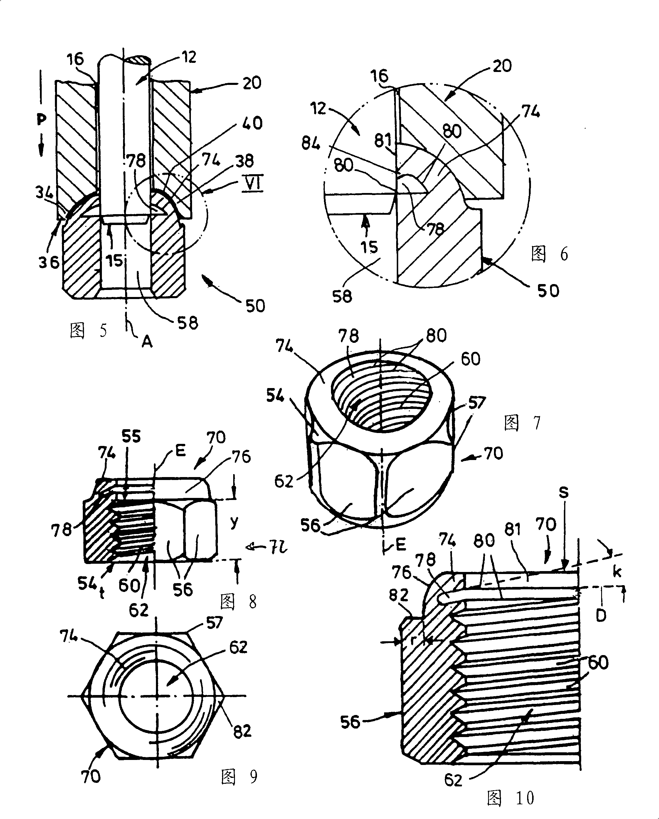
[0040] The metal tool 10 that is used to process an annular workpiece 50 has punch 12, and its length a here is 76mm and diameter d is about 10mm, forms a central stop disc 14 from its upper end in Fig. 1, stop disc diameter d 1 Here it is 12 mm and the axial thickness b is 3 mm. The dimensions of the punch 12 and thus the diameter d of its pressing end face 15 depend on the diameter of the bore of the nut blank 52 which will be described later. The punch 12 is movably accommodated in a guide channel 16 of a sleeve-shaped housing 20 whose axial length h is here 78 mm and whose outer diameter c is approximately 22 mm. The diameter e of the guide channel 16 extending along the longitudinal axis A of the housing is slightly larger than the diameter d of the punch 12 .

[0041] At an axial distance n of 23 mm from the upper lip 32 of the cylindrical housing 20, an annular flange 24 is formed on the outer surface 22 thereof. In a radial plane D defined by its upper annular edge ...


PUM


Abstract

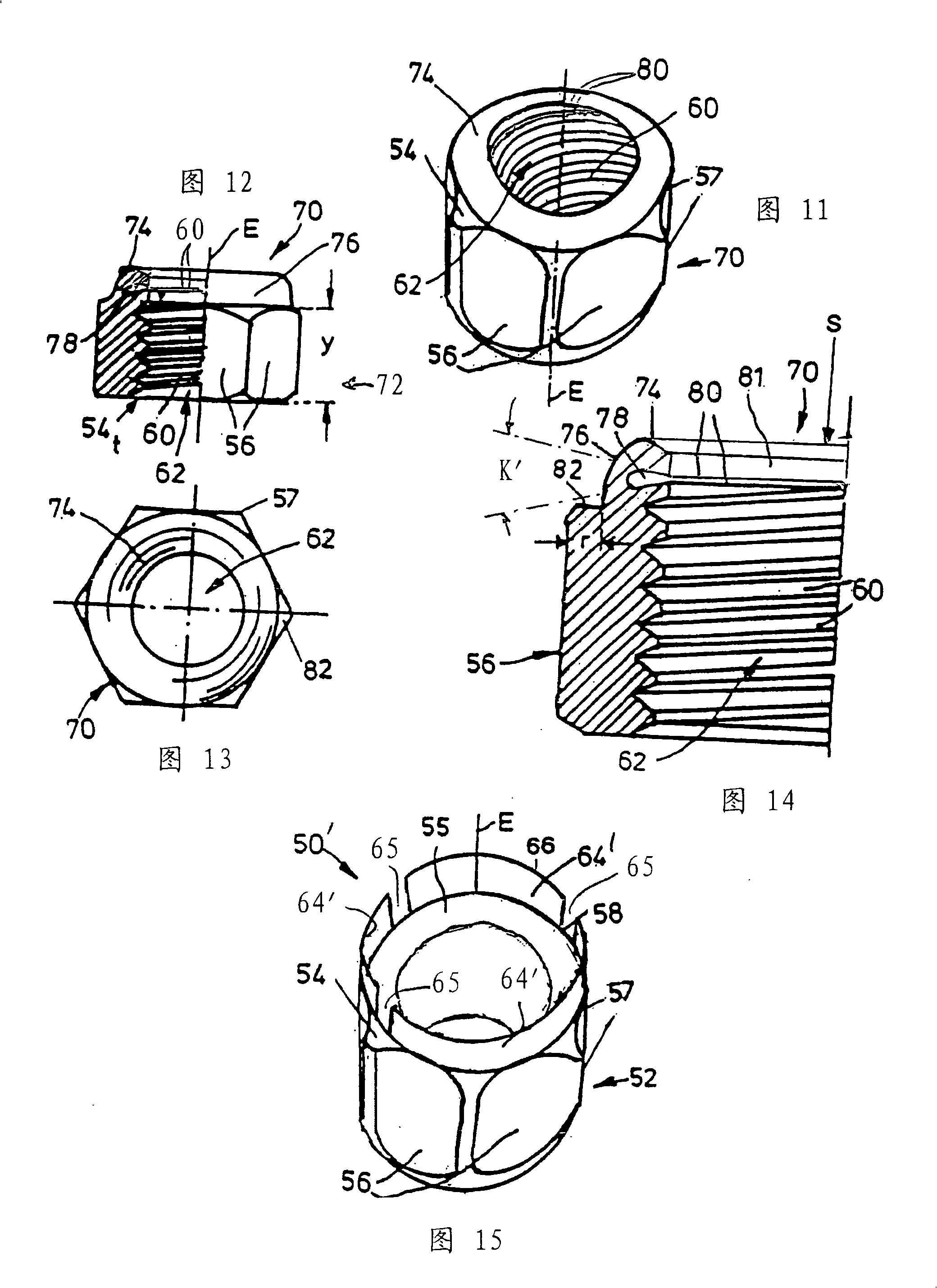
The invention relates to a screw nut from a metal material, which comprises a tapped hole (62) and an inner groove (78) which radially extends in relation to the longitudinal axis (E) thereof. An annular collar (64) is formed onto one of the faces (54) of the screw nut (70) and its cross-section is bent in the direction of the axis to such a degree as to delimit, together with a section of said face surrounding the tapped hole (62) as a contact surface (55), a receiving slot (78) that is directly associated therewith.

Description

technical field [0001] The invention relates to a nut made of metal material, having a threaded hole and an inner groove arranged radially and annularly with respect to its longitudinal axis. Furthermore, the invention includes a method of manufacturing said nut and a tool developed for this purpose. Background technique [0002] A nut of this type is known from German patent 305761, wherein, in order to form a lock nut, the nut is provided with an annular groove, which is realized by a boring tool on a machine tool with a rotating spindle, which is equipped with a chuck Used to hold odd or multiple nuts when grooving. Grooves are made prior to thread cutting. The grooves are located equidistant from both end faces of the nut. The threads are cut on both sides of the groove with the same pitch. After this, the nut is squeezed so that the threaded parts on both sides of the groove are displaced from each other. [0003] Swiss patent 249469 provides a lock nut which is gr...

Claims


Application Information

Patent Timeline
Patent Type & Authority Applications(China)
IPC IPC(8): F16B39/34F16B39/38
CPCF16B37/00F16B39/38
Inventor 哈特马特·弗莱格
Owner 哈特马特.弗莱格
Learn More