Optical sheet combination structure, surface emitting device, and liquid crystal device

A layered, surface-emitting technology, used in optics, optical components, lighting devices, etc.

Active Publication Date: 2009-01-07
SONY CORP
View PDF3 Cites 12 Cited by
  • Summary
  • Abstract
  • Description
  • Claims
  • Application Information

AI Technical Summary

Problems solved by technology

Therefore, a method is adopted to limit the light emission direc

Method used


Image

  • Optical sheet combination structure, surface emitting device, and liquid crystal device
  • Optical sheet combination structure, surface emitting device, and liquid crystal device
  • Optical sheet combination structure, surface emitting device, and liquid crystal device

Examples


Embodiment Construction

[0040] Specific embodiments of the present invention are described below with reference to the accompanying drawings.

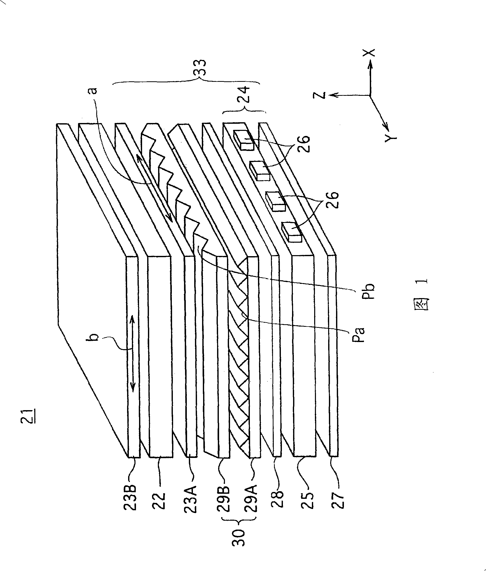
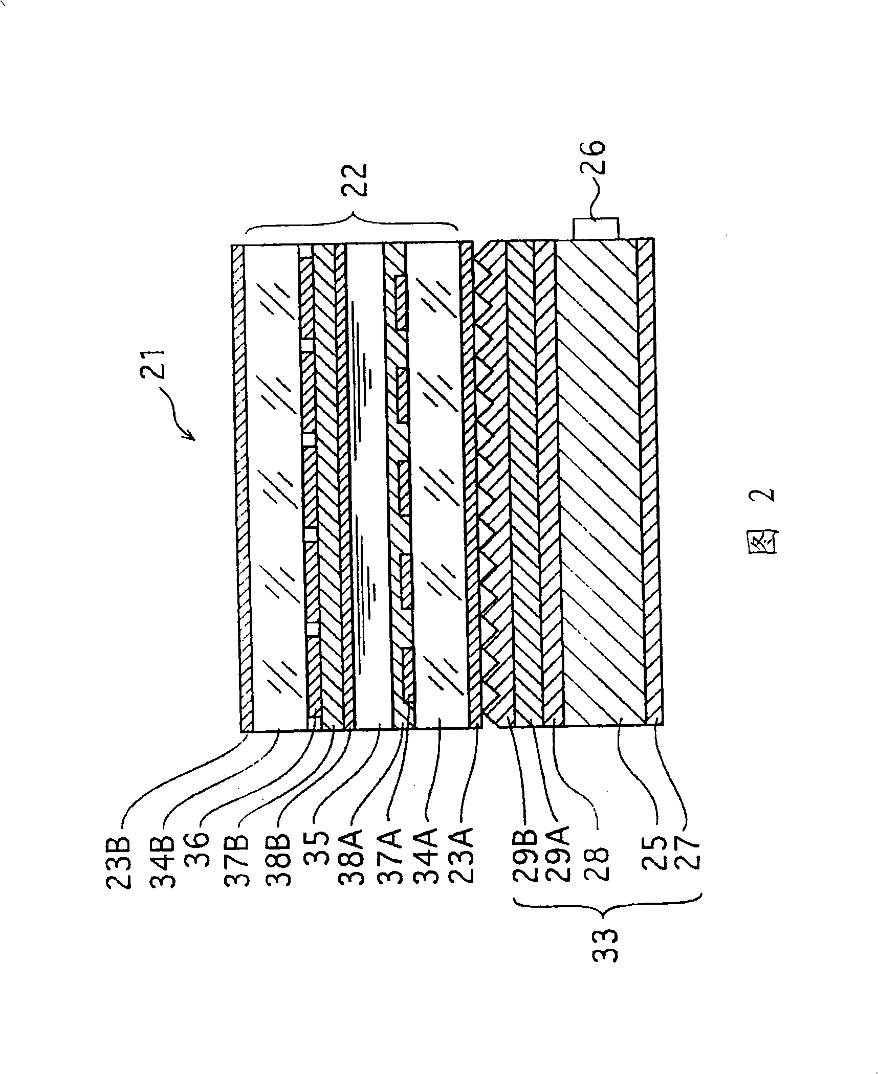
[0041] FIG. 1 is a perspective perspective view showing an outline structure of a liquid crystal display 21 equipped with an optical laminate structure 30 according to an embodiment of the present invention. FIG. 2 is a cross-sectional view showing the outline structure of the liquid crystal display 21 . First, the overall structure of the liquid crystal display 21 is described.

[0042] The liquid crystal display 21 of the present embodiment includes a liquid crystal display panel 22 , first and second polarizers 23A and 23B sandwiching the liquid crystal display panel 22 , and a surface light emitting device 33 . The surface light-emitting device (backlight device) 33 is composed of the surface light-emitting unit 24, the diffusion sheet 28, the optical laminated structure 30 of the present invention, and the first polarizer 23A.

[0043] As shown in FIG....


PUM

PropertyMeasurementUnit
Thicknessaaaaaaaaaa

Abstract

The invention relates to an optical sheet combination structure disposed between a polarizer and a surface emitting unit, which includes a first optical sheet having a number of columnar cubic structures of curing resin arrayed on a transparent base, a valley portion between adjacent cubic structures contacting a surface of the transparent base, and a second optical sheet disposed nearer to the side of the polarizer than the first optical sheet, having a number of columnar cubit structures arrayed on a surface, and a refractive index of the cubic structures along an extension direction thereof being different from a refractive index of the cubic structures along an array direction thereof.

Description

technical field [0001] The invention relates to an optical sheet combination structure for improving brightness by using two optical sheets, a surface light-emitting device and a liquid crystal display equipped with the optical sheet combination structure. Background technique [0002] Liquid crystal displays (LCDs) can achieve lower power consumption than cathode ray tubes (CRTs), and are manufactured to be smaller and thinner. Liquid crystal displays of various sizes are now widely used in small devices such as mobile phones, portable game consoles, digital cameras, personal digital assistants (PDAs) and large-sized LCD TVs. [0003] Liquid crystal displays are classified into a transmissive type, a reflective type, and the like. A liquid crystal display, particularly a transmissive liquid crystal display, includes a liquid crystal display panel, a first polarizer (polarizing plate) disposed on the light incident side of the liquid crystal display panel, and a second pola...

Claims


Application Information

Patent Timeline
IPC IPC(8): F21V8/00F21V9/14G02F1/13G02F1/1335
CPCG02B5/045G02F2001/133507G02F1/133507G02B5/02G02B5/04G02F1/1335
Inventor 水野裕堀井明宏平井基介小幡庆星光成木村清广佐佐木纯
Owner SONY CORP
Why Eureka
Try Eureka