
Hand prosthesis

A finger prosthesis and palm technology, applied in the field of hand prosthesis, can solve the problems of troublesome, high susceptibility to interference, etc., and achieve the effect of stable pressure and reliable grip

Active Publication Date: 2011-05-04
OTTO BOCK HEALTHCARE IP GMBH & CO KG
View PDF2 Cites 0 Cited by
  • Summary
  • Abstract
  • Description
  • Claims
  • Application Information

AI Technical Summary

Problems solved by technology

Disadvantages are the high control effort for each individual finger, the complicated technology with drives integrated in the fingers, and the high susceptibility to interference due to the complex design

Method used


Image

  • Hand prosthesis
  • Hand prosthesis
  • Hand prosthesis

Examples


Embodiment Construction

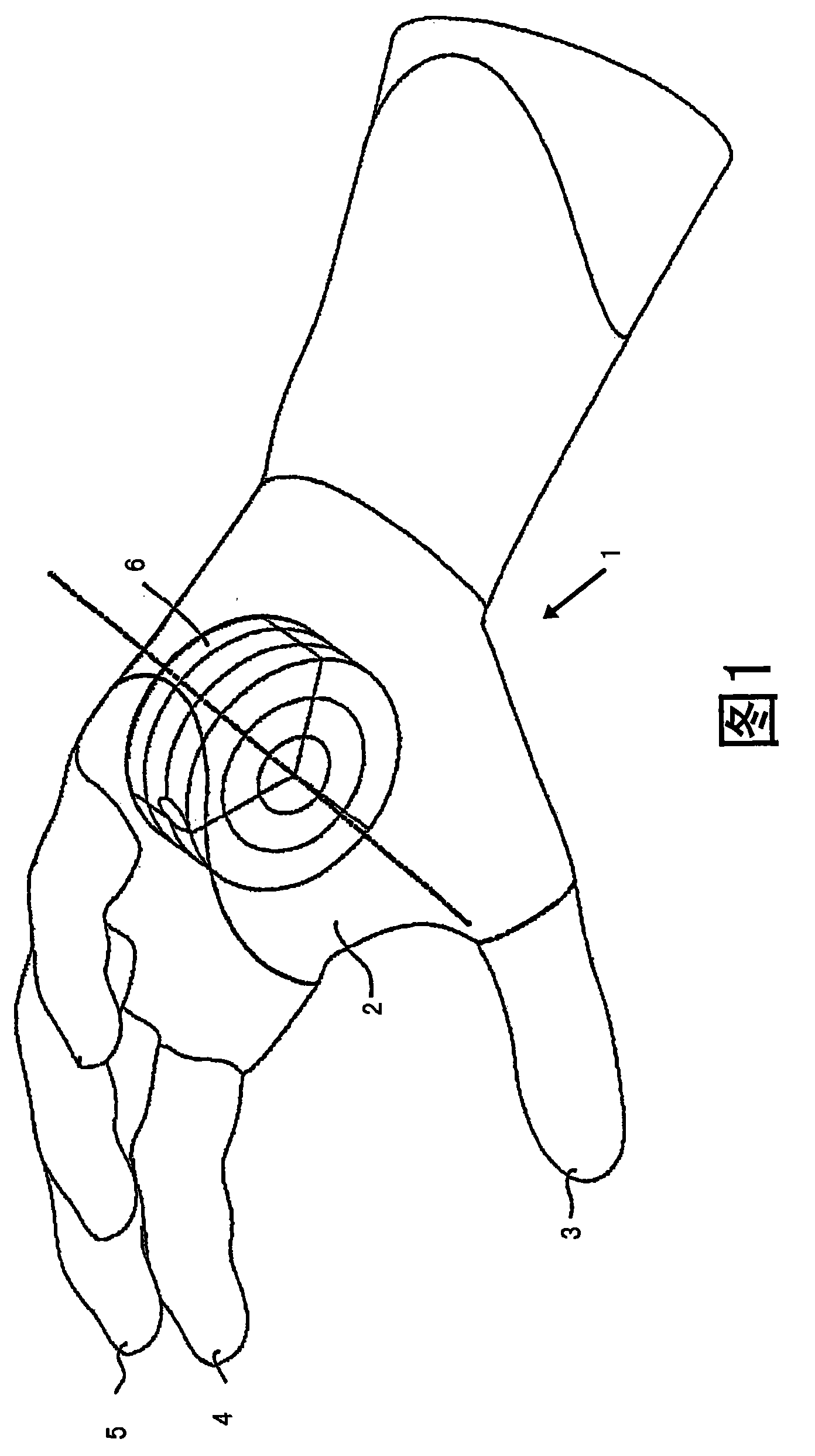
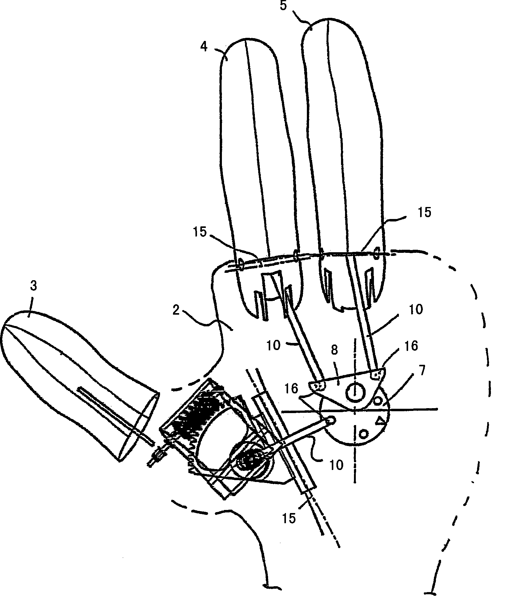
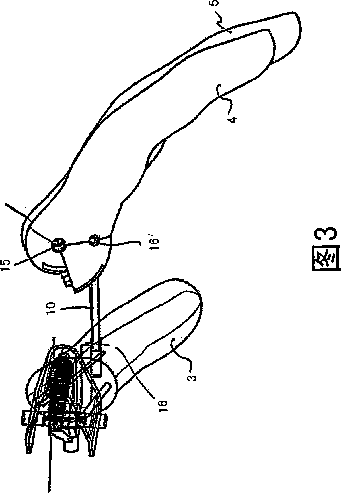
[0023] FIG. 1 shows a hand prosthesis 1 comprising a hand base frame 2 and at least three finger prostheses 3 , 4 , 5 mounted on the hand base frame 2 in an articulated manner. The finger prostheses 3, 4, 5 correspond to the thumb, index and middle fingers of a natural hand. The movable bearings of the three finger prostheses 3 , 4 , 5 , which can be actuated by a common drive 6 , are sufficient to perform multiple gripping tasks of the hand. The remaining two fingers, the ring finger and the little finger, can move passively together and are made of elastomer material in order to achieve as natural a feel as possible. The drive unit 6 in the form of an electric motor and its associated transmission are mounted inside the hand base frame 2 . An energy source (not shown) for the drive device 6 can also be arranged inside the hand base 2 . The drive device 6 is controlled via a control device which can be arranged in the hand base 2 . Corresponding signals can be generated by...


PUM


Abstract

The invention relates to a hand prosthesis comprising a chassis to which a plurality of finger prostheses are articulated, said finger prostheses being movable about at least one swiveling axis relative to the chassis and towards each other by means of a drive. The aim of the invention is to provide a hand prosthesis which has a simple control mechanism, works reliably and can be produced at low cost. For this purpose, the force transmission devices (10) on a common drive (6) are coupled to the finger prostheses (3, 4, 5) in such a manner that starting from a rest position and depending on the direction of rotation of the drive (6) at least two finger prostheses (3, 4, 5) go through different angles of adjustment relative to the chassis (2).

Description

technical field [0001] The invention relates to a hand prosthesis having a base frame on which a plurality of finger prostheses are mounted in an articulated manner and which can be moved relative to the base frame and towards each other via a drive about at least one pivot axis. sports. Background technique [0002] The task of a hand prosthesis is to replace the appearance and function of the hand that has to be replaced in as natural a manner as possible. For this purpose, the hand prosthesis must be able to displace the gripping devices, which can be configured as finger simulators, relative to one another in order to be able to grip objects. [0003] A two-finger grip is known from US 2004 / 00195638 A1, in which two gripping devices can be displaced from an open position into a closed position in which the The gripping devices are directly opposite each other. Objects located between the gripping devices can thus be retained. To release the grip, the direction of rot...

Claims


Application Information

Patent Timeline
Patent Type & Authority Patents(China)
IPC IPC(8): A61F2/68A61F2/58
CPCA61F2/583A61F2/586A61F2002/30523A61F2002/30525A61F2002/5018A61F2002/5055A61F2002/5093A61F2002/587A61F2002/701A61F2220/0025
Inventor G·普奇哈默
Owner OTTO BOCK HEALTHCARE IP GMBH & CO KG
Learn More