Tensioned inflatable cover module

a technology of inflatable cover and spherical plate, which is applied in the direction of plant protection, building components, shaping building parts, etc., can solve the problems of limited scale or expanse of coverage of current greenhouse designs, laborious assembly of apparatuses, and small air volume enclosed by current greenhouse designs, etc., to achieve unprecedented ground and space coverage, facilitate shrinkage of length, and steady tension

Inactive Publication Date: 2009-07-21
KASSIANOFF EDOUARD PICHKO
View PDF34 Cites 12 Cited by
  • Summary
  • Abstract
  • Description
  • Claims
  • Application Information

AI Technical Summary

Benefits of technology

[0007]The Tensioned Inflatable Cover Module is an inflatable apparatus or assembly thereof designed to provide reliable control of the flow of fluids and radiation between an enclosed space and its surroundings. Essentially the invention comprises an inflatable tube mounted on end supports that can move along end fluid conduits, the conduits being fluidly-connected to the tube. One conduit is open for transit of inflation fluid in and out of the inflatable tube and another conduit is closed to retain fluid within the apparatus. End covers and the tube's movable supports are provided to compensate for and facilitate shrinkage of the length of the inflatable tube, which occurs upon inflation. Steady tension is maintained on the inflatable tube by the squeezing action of peripheral elastic cinctures and the tugging of springs on the tube's end supports, from a minimum deflated bundle outer diameter to a substantially larger inflated outer diameter. A structural, tensionable member secures the conduits together. Conduits are in turn adjustably secured either to building frames or to peg-like anchors, which may be driven into the ground or fastened to building frames, posts and the like. The desired size of gaps between adjacent modules of an assembly can be set at installation on site and can be controlled in operation by varying the extent of tube inflation. Control of the size of the gaps in turn affords control of the flow of fluids and radiation between the enclosed space and its surroundings. The Tensioned Inflatable Cover Module is particularly suited for novel inflatable building structures that can span natural and man-made depressions, e.g. canyons, craters, valleys, coulees, embankments and the like, to provide unprecedented scale of ground and space coverage. Other uses include insulation, shutters, shelters, and cover for greenhouse frames.

Problems solved by technology

Among inflatable buildings, greenhouses offer great challenges in design because of the need, on one hand, to allow radiation into the enclosed space for plant growth, and on the other hand also regulate temperature within the often tight limits that are compatible with the biology of the plants being grown.
Current greenhouse designs suffer from limitations in scale or expanse of coverage attributable mostly to the need for a construction frame to support the transparent cover and means for ventilation in the form of motorized fans and shutters.
Another limitation to the scale of environment control is the economics that dictate heating the minimum volume of air necessary for plant growth.
The small air volumes enclosed by current greenhouses provide little buffering against variations in external climatic factors such as radiation, temperature, wind and precipitation.
The apparatus is laborious to assemble and necessitates additional equipment for ventilation in the form of motorized fans and shutters.
All the aforesaid designs are limited to small scale, mostly indoor applications mainly because of their dependency on a supporting frame and the lack of rugged integral means for module support.
These designs also lack dependable means of maintaining openings between the tubes in windy outdoors conditions mostly because they utilize gravity-dependent mechanisms of tube deflation.
Deflation of the tube per se does not automatically provide consistent gaps between modules because the tubes tend to flatten, sag and flap in the wind.
U.S. Pat. No. 3,328,926 to Reinhard (1967) does not disclose any reliable or consistent method of achieving ventilation gaps between inflatable tubes, upon deflation.

Method used


Image

  • Tensioned inflatable cover module
  • Tensioned inflatable cover module
  • Tensioned inflatable cover module

Examples


Embodiment Construction

Scope and Materials

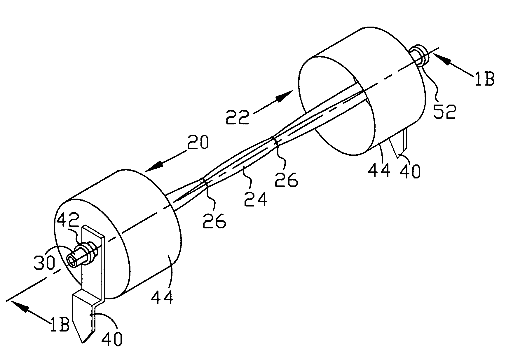
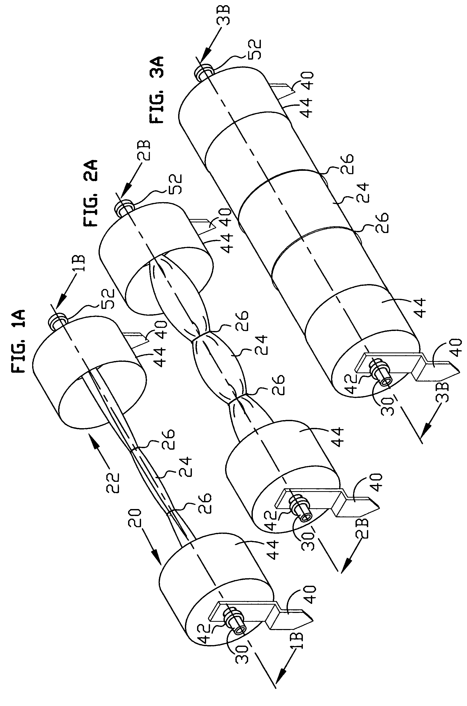
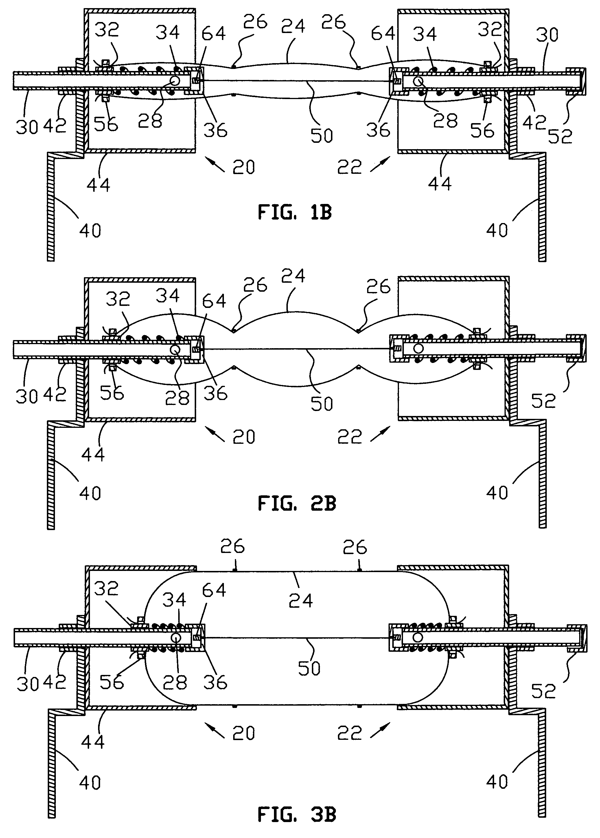
[0086]The present invention relates to buildings and more particularly to a novel, modular inflatable building particularly adapted for use as a greenhouse, shelter and the like. Materials suitable for constructing the Tensioned Inflatable Cover Module are well known to those skilled in the art. Essentially one needs fasteners, inflatable tubes, cables or ropes, springs, bars, sheets and tubing. Inflatable covers for greenhouses are usually made out of polymers e.g. clear polyethylene. However, where light is not required other flexible material, e.g. fabric, opaque polymers, may be used to construct the inflatable tubes. Other components of this module can be made out of sheets, tubing and bars of metal, polymer or composite, which may be cut to size, shaped, drilled, threaded, glued, or welded for fastening. Current plumbing supplies or like products can also be used. The choice of materials is only limited by the intended use and engineering considerations and ...


PUM


Abstract

Modular inflatable cover for buildings, comprising separate coaxial conduits (30) secured together by tensionable link (50) and fluid-connected by coaxial inflatable tube (24). Tube (24) securely embraces sliders (32) that in turn closely but freely embrace conduits (30). Sliders (32) are urged by springs (34) to keep tube (24) taught. Elastic cinctures (26) on tube (24) and springs (34) tensionably cooperate against inflation means to provide reliable control of openings between adjacent modules in an assembly. Conduits (30) are securely torqued to ground anchors (40) by coupling (42). End covers (44) and sliders (32) are provided to compensate for and facilitate length shrinkage of tube (24), upon inflation. The present invention provides a variable cover with integral support that is uniquely capable of exploiting canyons and other ground depressions for an unprecedented scale of environment control. Applications include greenhouses, shutters, insulation and shelters.

Description

BACKGROUND OF THE INVENTION[0001]1. Field of the Invention[0002]The Tensioned Inflatable Cover Module relates to inflatable buildings and in particular to systems for regulating the flow of fluids and radiation into enclosed spaces as provided, for example, in greenhouses and shelters.[0003]2. Description of the Prior Art[0004]Inflatable buildings have been used extensively in the greenhouse and leisure industries where the relatively low weight, cost and ease of installation are major advantages over more rigid structures built of glass or composite materials. The purpose of these installations has been primarily the provision of more or less controlled environments for plant growth or human activities; an increasingly popular benefit of these microclimate zones has been public enjoyment as provided in garden centers, botanical gardens and sports complexes. With the unabating current deforestation worldwide and the consequent environment degradation, these oasis of life may become ...

Claims


Application Information

Patent Timeline
Patent Type & Authority Patents(United States)
IPC IPC(8): E04G11/04
CPCE04B1/74A01G9/1415Y02A40/25
Inventor KASSIANOFF, EDOUARD PICHKO
Owner KASSIANOFF EDOUARD PICHKO
Why Eureka
Try Eureka