
Shift arrangement having a shift fork

A technology of shifting forks and forks, applied in the direction of components with teeth, control/adjustment systems, mechanical control devices, etc., can solve problems such as weight increase, and achieve the effect of correcting bending errors and improving vertical accuracy

Inactive Publication Date: 2009-01-14
SCHAEFFLER TECH AG & CO KG
View PDF2 Cites 9 Cited by
  • Summary
  • Abstract
  • Description
  • Claims
  • Application Information

AI Technical Summary

Problems solved by technology

[0007] The stronger the components, the less this deformation, however this also leads to an undesired increase in weight

Method used


Image

  • Shift arrangement having a shift fork
  • Shift arrangement having a shift fork
  • Shift arrangement having a shift fork

Examples


Embodiment Construction

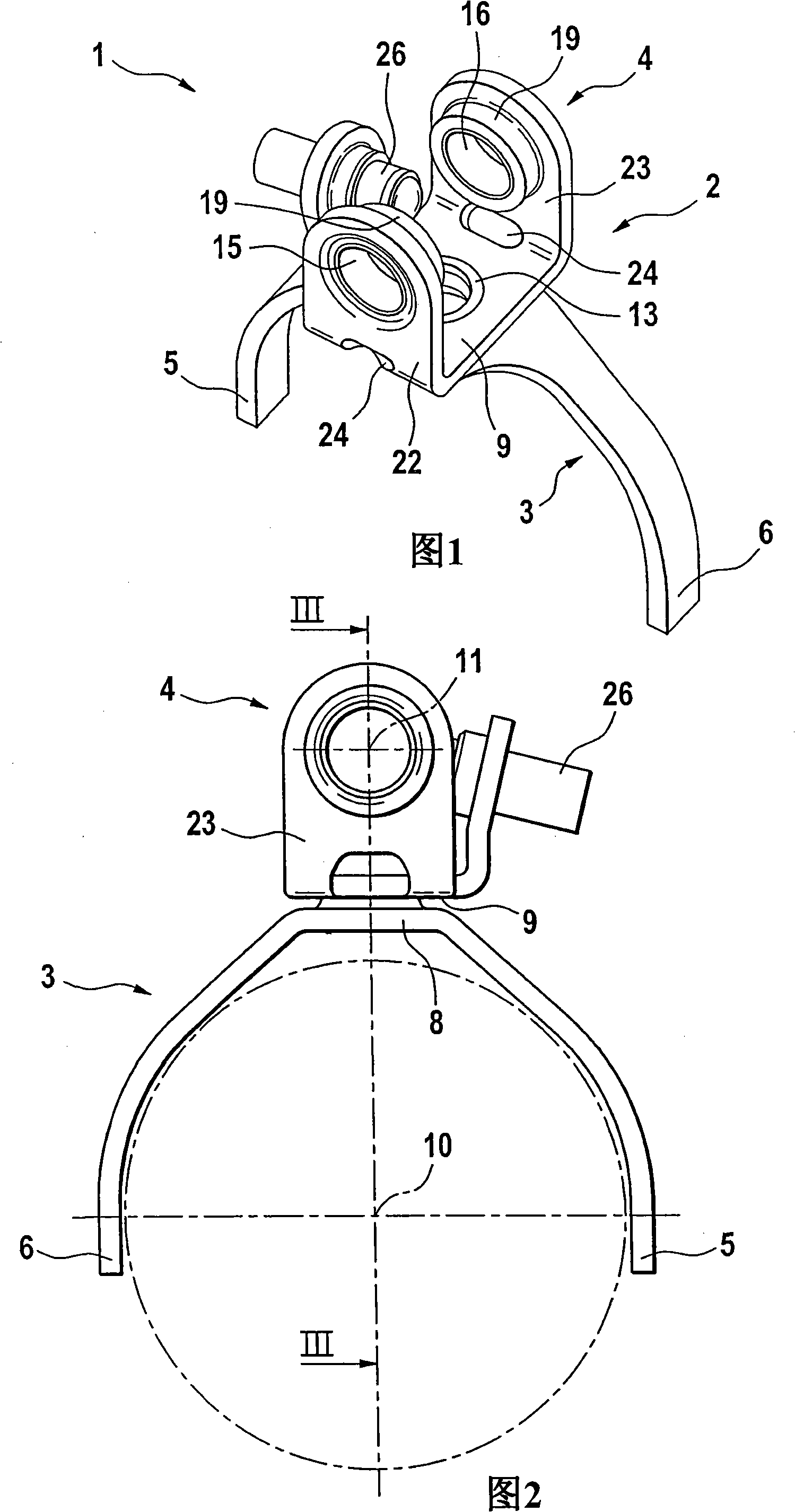
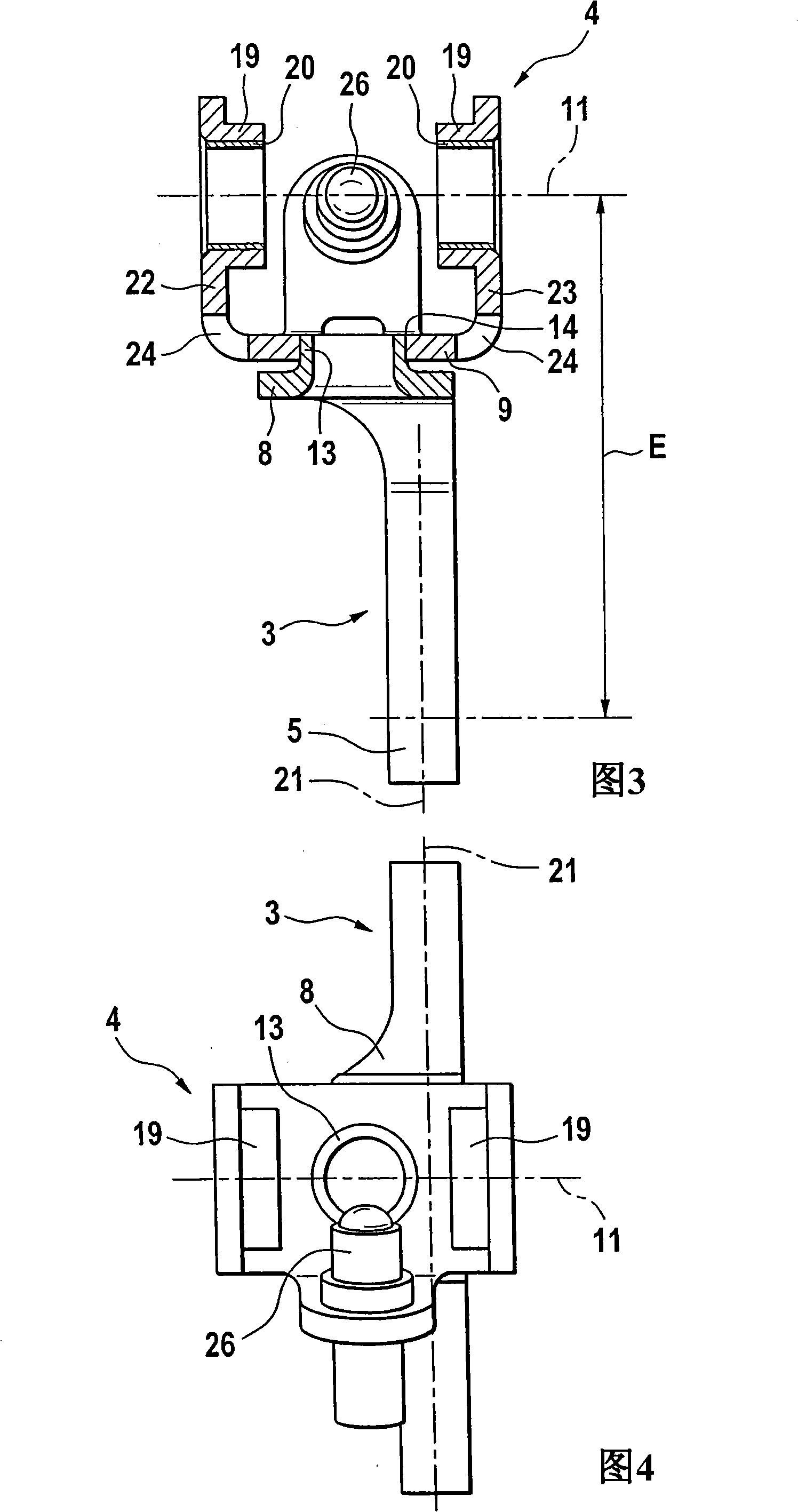
[0024] The exemplary embodiment of the shifting system 1 according to FIGS. 1 to 4 has a shifting fork 2 with a shifting fork base body 3 and a guide 4 , and a shifting link (not shown) along the shifting The link axis 11 is oriented. The selector fork base body 3 is a fork-shaped sheet metal profiled part with fork heads 5 and 6 which enclose sliding sleeves (not shown or shown only in outline), the sliding sleeves The axis of rotation is denoted by reference numeral 10 .

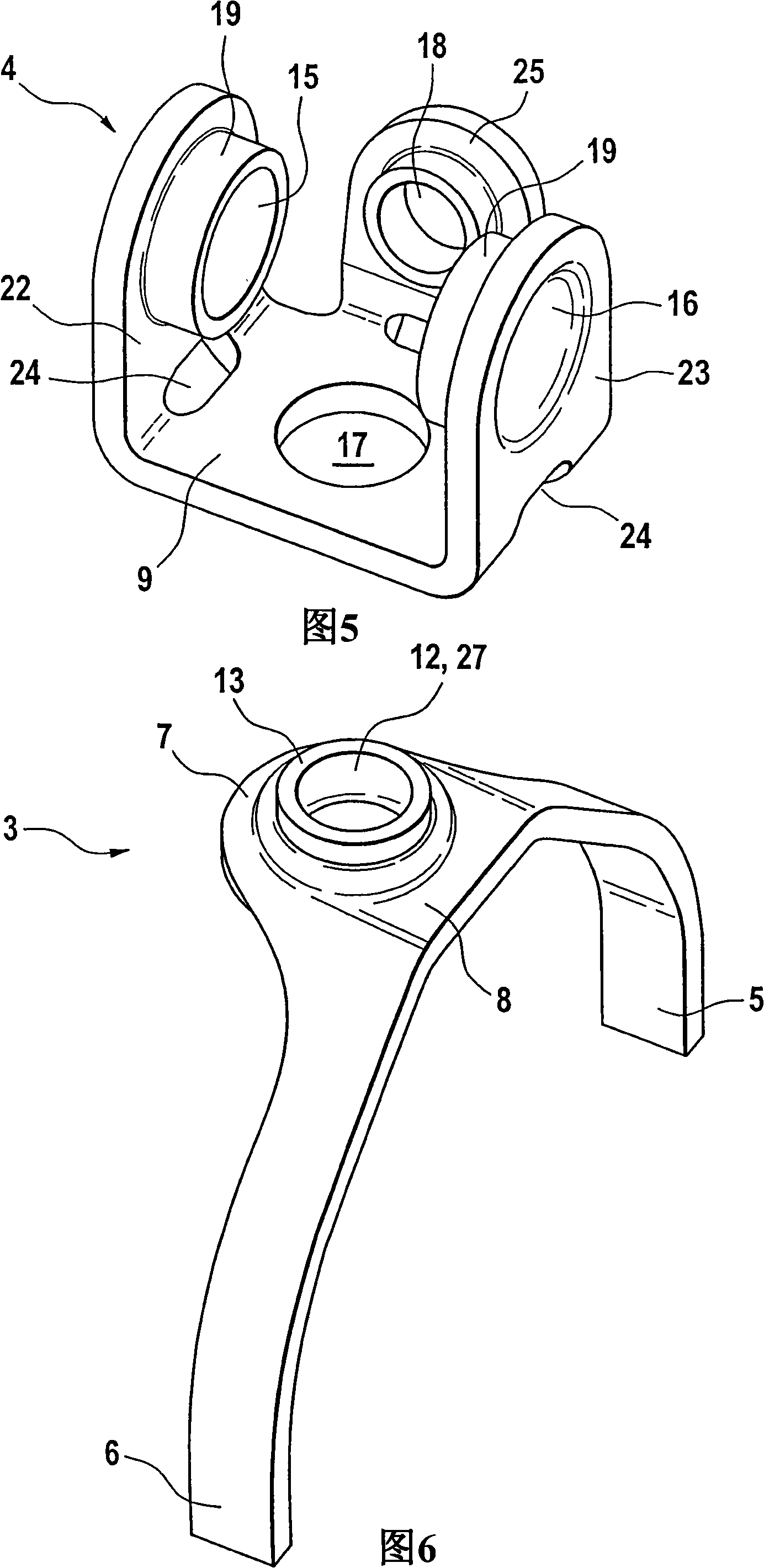
[0025] The shift fork base body 3 ( FIG. 6 ) is shaped in such a way that it has a central region 8 between the fork heads 5 and 6 on the face 7 facing away from the sliding sleeve, the central region 8 with its shape engaging the base 9 of the guide 4 . In the central region 8 , the shift fork base body 3 has a shift fork recess 12 , which is formed as a penetration point 27 , so that a circumferential edge 13 terminates the shift fork on the face 7 facing away from the sliding sleeve. Substrate 3.

...


PUM


Abstract

The invention relates to a shift arrangement having a shift member of a change-speed transmission and a shift fork (2) which engages into a shift sleeve, comprising at least of a guide (4), which is arranged on the shift member and has at least one guide recess (16) whose shape is complementary to the shift member, and a shift fork base body (3), wherein the shift fork base body (3) has opposite fork ends (5,6) which engage around the shift sleeve, and the guide (4) has at least three recesses (15,16,17), the first and second recesses (15,16) as a through recess hold the shift member, and the third recess (17) holds the shift fork base body (3).

Description

technical field [0001] The invention relates to a shifting system with a shifting link of a transmission gear transmission and a shifting fork engaged in a sliding sleeve, the shifting fork is composed at least of a shifting fork base and is arranged on the shifting link The guide part on the guide part has a guide part notch, and the shape of the guide part notch is complementary to the shift link, wherein the shift fork base has mutually opposite forks, and the forks surround the shift sleeve. Background technique [0002] In a manual or automatic transmission, a synchronizer housing and a selector sleeve are arranged between two gearwheels mounted rotatably on a transmission shaft. The shift sleeve is provided with internal teeth which mesh with external teeth applied on the synchronizer housing. The synchronizer housing is connected in a rotationally fixed manner to the drive shaft. During a gear change, the shift sleeve is moved axially toward one of the range gears u...

Claims


Application Information

Patent Timeline
IPC IPC(8): F16H63/32
CPCF16H2063/327F16H2063/321F16H63/32
Inventor 斯坦尼斯拉夫·马西尼
Owner SCHAEFFLER TECH AG & CO KG
Learn More