Power-driven hand tool

A hand-held device and power-driven technology, which is applied in metal processing equipment, grinding/polishing equipment, portable motorized devices, etc., can solve the problem that it is not enough to bear a huge load, and achieve the effect of large torque transmission and high clamping force

Inactive Publication Date: 2009-01-21
C & E PANYIN CO LTD
View PDF3 Cites 24 Cited by
  • Summary
  • Abstract
  • Description
  • Claims
  • Application Information

AI Technical Summary

Problems solved by technology

However, the clamping forces achievable with this known clamping device were found to be generally insufficient at high loads to accommodate the extremely high loads required for the application, especially with vibratory drives such as saws and cutting tools. huge loads

Method used


Image

  • Power-driven hand tool

Examples


Embodiment Construction

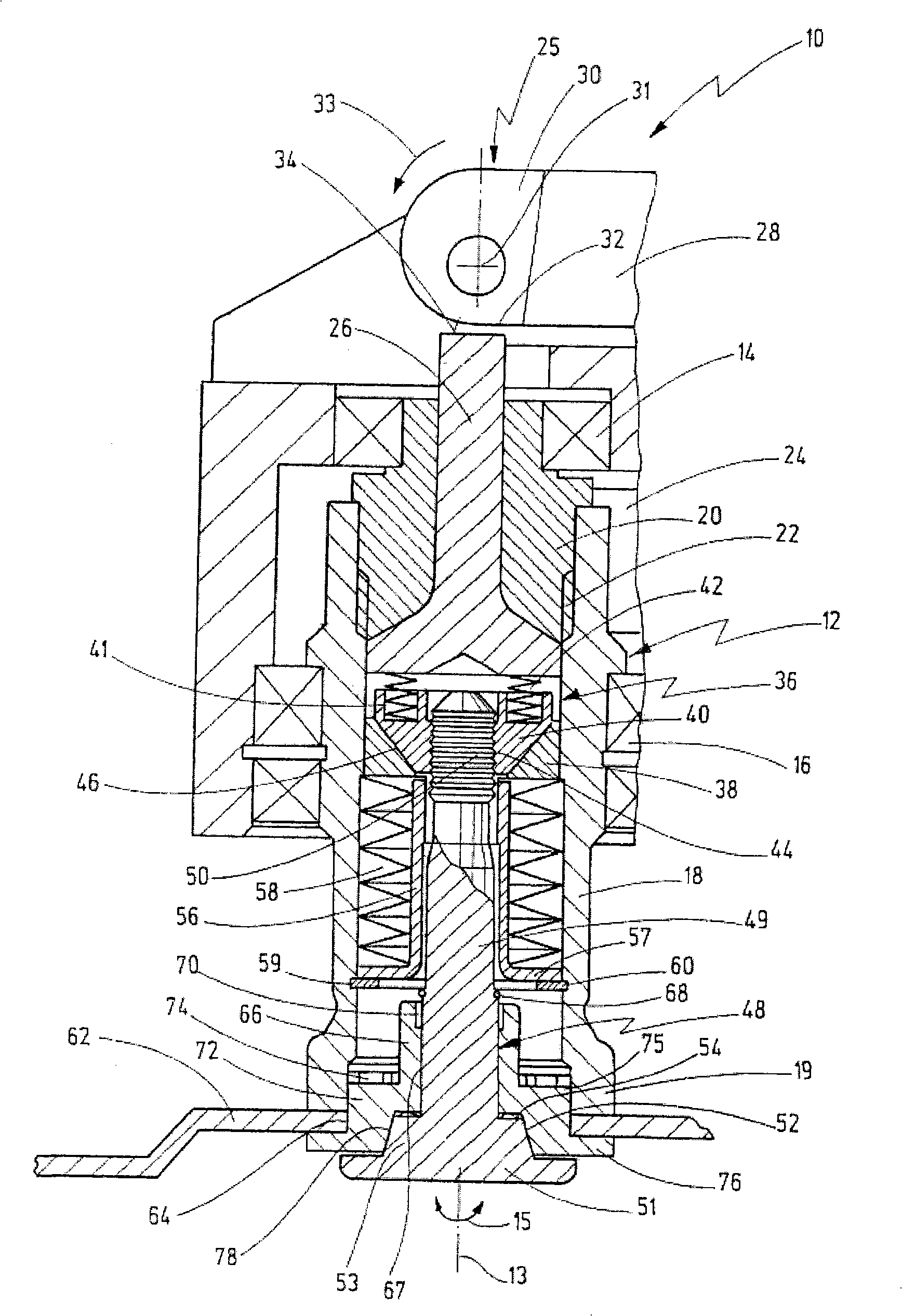
[0041] figure 1 A cross-sectional view of the working head region of the powered handheld device 10 according to the present invention is depicted. The hand-held device 10 includes a drive shaft 12, and the tool 62 is fixed on the outer end of the drive shaft 12 by using a clamping unit, which will be described in detail later.

[0042] The drive shaft 12 is excited by the eccentrically driven vibrating fork 24 to vibrate, and the specific method will not be described in detail here. As indicated by the double arrow 15, the drive shaft 12 vibrates around its longitudinal axis 13 at a high frequency of approximately 10,000 to 25,000 vibration cycles per minute and at a small angle of between approximately 0.5° and 7°.

[0043] Handheld devices 10 driven to vibrate as such have recently been put into many special uses, such as vibrating cutters for cutting automotive vehicle panels, vibrating saw blades for sawing, milling, and many others.

[0044] In contrast to what is enco...


PUM


Abstract

A power-driven hand tool comprises a drive spindle adapted to drive a tool, that can be driven to oscillate about its longitudinal axis, which tool can be fixed on a retaining section of the dive spindle by a securing element, and further comprises a displacing device that serves to displace the securing element between a releasing position in which the securing element can be released from the drive spindle and a clamping position in which the securing element is clamped on the retaining section by a spring element, the securing element comprising a clamping shaft adapted to be inserted into the securing element, which is axially fixed in the drive spindle for clamping the tool in the clamping position, and which can be detached in the releasing position. For clamping of the tool a split chuck is provided which is clamped on the retaining section by the securing element in the clamped position and is connected with the retaining section in form-locking engagement.

Description

technical field [0001] The invention relates to a powered hand-held device comprising a motor-controlled drive shaft adapted to drive a tool held on its retaining portion by a locking element. The hand-held device includes movement means for moving the locking element between a release position, in which the locking element is releasable from the drive shaft, and a clamping position, in which the locking element is held in place by a spring element. On the holding part, the locking element includes a clamping shaft adapted to be inserted into the locking element, fixed on the drive shaft in the axial direction to clamp the tool in the clamping position, and detachable in the releasing position. Background technique [0002] A similar powered handheld device is available from patent WO 2005 / 102605A1. [0003] With this known hand-held device, the locking element can be inserted into the drive shaft through the fitting opening of the tool and fixed thereon, thereby securing t...

Claims


Application Information

Patent Timeline
Patent Type & Authority Applications(China)
IPC IPC(8): B25F5/00B24B45/00B24B23/02
CPCB24B45/006B24B23/022
Inventor 居尔根·布利克尔乌卫·弗鲁艾
Owner C & E PANYIN CO LTD
Why Eureka
Try Eureka